Common precision measuring tool errors
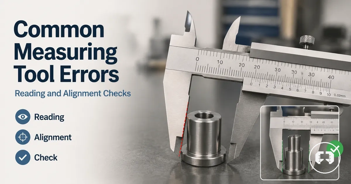
Precision measuring tool errors are measurement mistakes that reduce reading reliability, repeatability, and confidence in the measured result. They usually appear when user technique, reading interpretation, alignment, calibration state, workpiece surface, or the measurement environment interrupts a consistent measuring process and creates inaccurate readings.
The problem is not always the tool itself, because the same measuring error can come from pressure, contact, a zero reference, a dirty surface, or a display reading that was interpreted too quickly. Error severity depends on the tool type, tolerance requirement, operator technique, workpiece condition, and measurement environment. A user-controlled cause is usually something that can be checked during setup or measurement, such as alignment, pressure, contact, or reading interpretation. A tool-condition cause may involve calibration state, wear, drift, or damage that needs verification before recalibration or replacement is considered.
If precision measuring tools give different readings on the same workpiece, the first diagnostic question is whether the result changes with the operator, the tool position, or the surrounding conditions. That distinction helps separate avoidable operator error from a possible tool error and prepares the next section: why precision measuring tools give inaccurate readings.
Why precision measuring tools give inaccurate readings
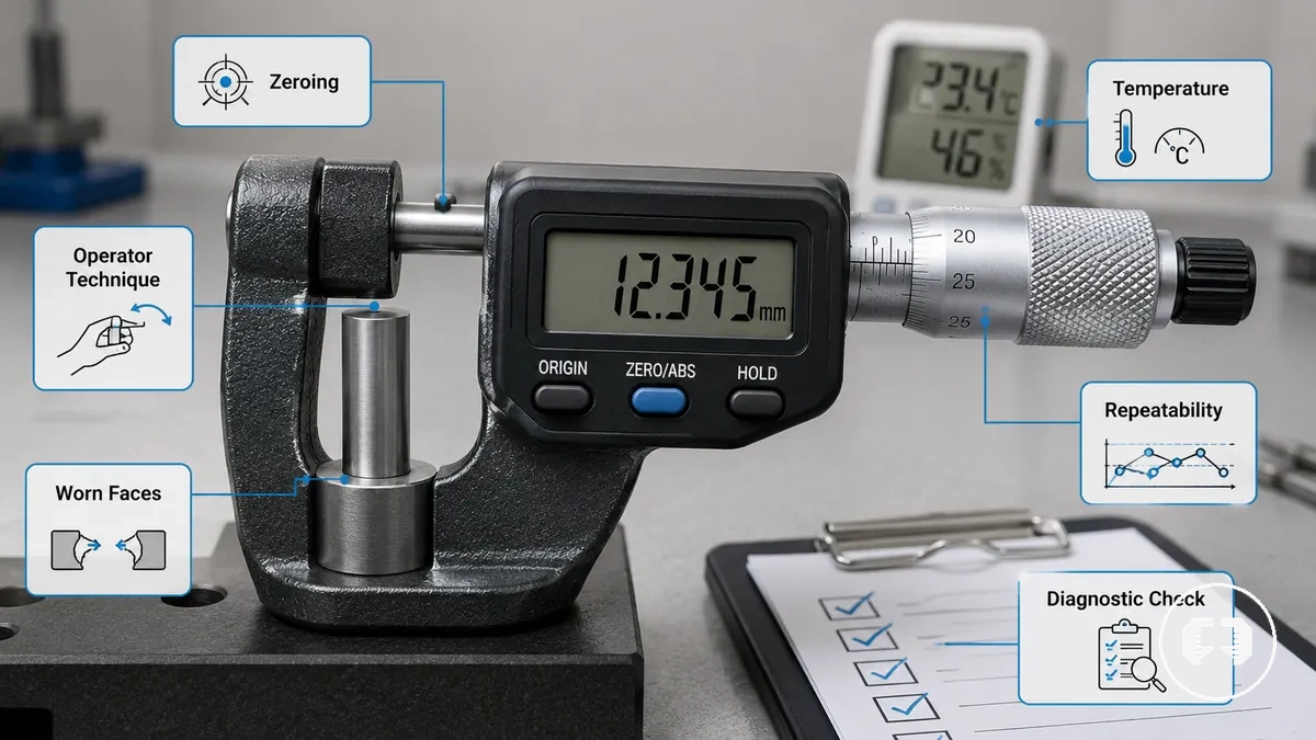
When inaccurate readings appear, different error sources can produce the same symptom, so the measured result should be diagnosed before a single cause is assumed. Precision measuring tools may lose repeatability when zeroing, operator technique, instrument condition, or the measurement environment affects the measurement process. These broad cause categories provide the most reliable starting point for troubleshooting.
Why precision measuring tools give inaccurate readings becomes easier to diagnose when each symptom is grouped by its likely cause and effect instead of by tool type. Understanding accuracy and repeatability factors helps explain why similar symptoms may require different diagnostic checks under different measuring conditions.
| Error source | Common condition | Reading symptom | First check |
|---|---|---|---|
| Zeroing | Incorrect zero reference or zero shift | Measured result shows a consistent offset | Verify the zero reference before measuring |
| Operator technique | Incorrect force, angle, or contact | Inconsistent result or reduced repeatability | Repeat the measurement using consistent technique |
| Instrument condition | Worn faces or possible drift | Unstable reading or reduced repeatability | Perform a diagnostic check and verify the calibration state |
| Measurement environment | Temperature changes, vibration, or debris | Measured result changes between readings | Inspect the workpiece and surrounding conditions |
The table classifies each error source by condition, symptom, and the first diagnostic check rather than implying one exact cause. Poor zeroing can lead to a shifted reference, worn faces can reduce repeatability, and unstable temperature may affect the measured result. Because similar symptoms can arise from different conditions, the diagnostic check helps identify the most likely explanation before further action is taken.
For example, an unstable reading may come from inconsistent operator technique during one measurement or from instrument drift during another, even though the symptom appears the same. Checking technique, tool condition, and the surrounding environment in sequence helps separate these possibilities. For broader guidance on related equipment and measurement topics, visit the precision measuring tools hub.
User technique, instrument condition, and environment as error sources
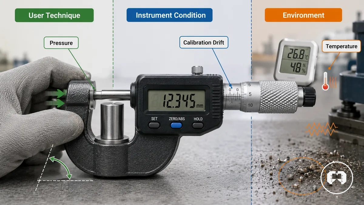
When the same inaccurate reading appears, the source may be user technique, instrument condition, or the environment rather than a single fault. Changes in pressure, angle, wear, calibration drift, temperature, vibration, or debris can affect reading confidence in different ways. Distinguishing these three source classes helps narrow the likely cause without assuming an exact diagnosis.
The comparison below separates the three source classes so similar reading behavior can be evaluated by likely origin instead of by symptom alone. Because different conditions can produce overlapping results, the first check should help distinguish the source before further troubleshooting.
| Source class | Typical condition | Reading behavior | What to check |
|---|---|---|---|
| User technique | Uneven pressure, incorrect angle, or inconsistent contact | Measured values may vary between repeated checks | Review handling, contact, and measuring position |
| Instrument condition | Wear or calibration drift | Repeatability may decrease or a zero shift may appear | Inspect tool condition and verify calibration state |
| Environment | Temperature changes, vibration, debris, or humidity | Reading confidence may change between measurements | Check the workpiece and surrounding conditions |
Reading and scale interpretation errors
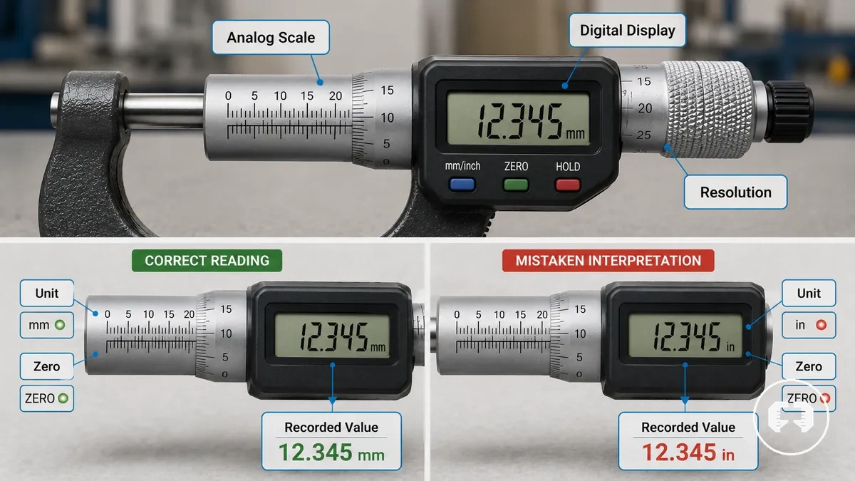
Reading and scale interpretation errors can create measurement error even when the tool and workpiece are otherwise suitable. A visible mark or number may be recorded incorrectly if scale interpretation, the digital display, unit switching, zero reading, or resolution is misunderstood. This section focuses on scale, display, and unit interpretation rather than tool condition.
Simple reading checks can reduce the risk of recording the wrong value before it is compared with a tolerance or documented. The annotated example below shows how reading and scale interpretation errors can occur when the visible mark, unit label, or display state is interpreted incorrectly.
- Confirm the selected unit before recording the measured value, especially after unit switching.
- Verify the zero reading before taking or repeating a measurement.
- Check the analog scale, vernier, or dial against the intended reference mark.
- View the scale from a suitable viewing angle to reduce scale reading mistakes.
- Consider the tool's resolution before recording the final value.
On an analog scale, the pointer or vernier may align correctly while the recorded value becomes incorrect if the wrong mark is interpreted. On a digital display, the visible number may be correct, yet the recorded value can still be wrong if the unit mode or zero state is overlooked. These examples show that interpretation, rather than tool condition, can affect the recorded value.
This section highlights interpretation risks without becoming a complete reading tutorial for every measuring tool. For detailed techniques on interpreting scales and displays, see reading precision measuring tools. Understanding scale interpretation, zero reading, and resolution helps reduce recording mistakes while leaving detailed reading methods to the dedicated guide.
Parallax and viewing angle errors
Parallax error is a viewing-angle problem that changes how a pointer or scale mark appears to align with a reference mark. When the line of sight is not directly aligned with the scale, the apparent reading can differ even though the pointer has not moved. Eye position therefore influences the apparent alignment between the pointer and the scale mark.
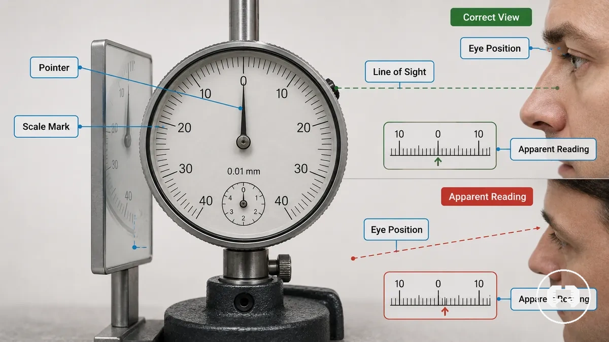
A common example occurs on an analog scale or dial where the pointer appears to align with a different scale mark when viewed from an angle instead of straight on. A mirrored scale, when available, can help the user align the line of sight more accurately, although the result still depends on correct eye position. Viewing the pointer directly in line with the scale mark helps reduce false apparent readings caused by viewing angle.
Digital display, unit, and zero-reading mistakes
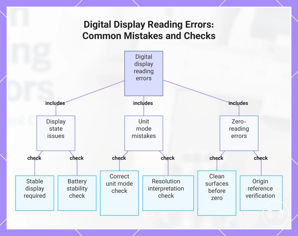
A digital display can still produce a wrong recorded value when the display state, unit mode, or zero reading is incorrect. A digital readout is not automatically error-free because an incorrect origin reference, unstable display state, or misunderstood resolution can lead to false confidence. Checking the display state, unit mode, and zero reference helps reduce these local reading mistakes.
Before accepting a digital display reading, verify these conditions:
- Confirm the display state is stable before recording the measured value.
- Check that the correct unit mode is selected.
- Verify the zero reading and origin reference before measuring.
- Ensure the measuring surfaces are clean before establishing the zero reference.
- Watch for battery stability or display behavior that may affect the displayed reading.
- Consider the tool's resolution when interpreting the recorded value.
These checks focus on display settings and interpretation rather than calibration. Skipping them can create false confidence even when the digital display appears to show a clear numerical value.
This chart shows the three main categories of digital display reading mistakes and the essential checks to avoid them.
Alignment, contact, and measuring force errors
When a measured value changes before it is read, the cause may be the way the tool contacts the workpiece rather than the workpiece itself. Misalignment, uneven contact, or excessive measuring force can shift the reading because the measuring faces do not engage the workpiece consistently. The main conditions to assess are alignment, contact, and measuring force.
Alignment, contact, and measuring force errors can be evaluated by examining the affected component and its contact condition. The table below summarizes how each condition may influence the measured result.
| Entity/part | Contact or force condition | Reading effect | Check |
|---|---|---|---|
| Jaws | Misaligned or tilted contact | May produce an undersized or unstable reading | Confirm full jaw alignment on the workpiece surface |
| Anvils or spindle faces | Excessive measuring force | May produce a compressed or shifted reading | Apply consistent measuring force |
| Measuring faces | Uneven contact | May produce unstable readings | Check that both measuring faces contact evenly |
| Workpiece surface | Uneven surface or inconsistent hand pressure | May change the measured result | Stabilize the workpiece and repeat the measurement |
Changing the contact condition can change the measured value even when the same tool and workpiece are used. Tilted jaws, uneven contact across the measuring faces, or increased hand pressure may alter contact with the workpiece surface, so the reading may become undersized, oversized, or unstable depending on the tool type, part geometry, and measuring force.
If the reading changes when the tool is repositioned while the workpiece remains unchanged, tool handling is often a more likely cause than the part itself. Repeating the measurement with consistent alignment, contact, and measuring force can help distinguish handling-related reading shifts. Following the proper use of measuring tools also helps maintain consistent contact conditions during measurement.
Caliper jaw alignment and unstable contact
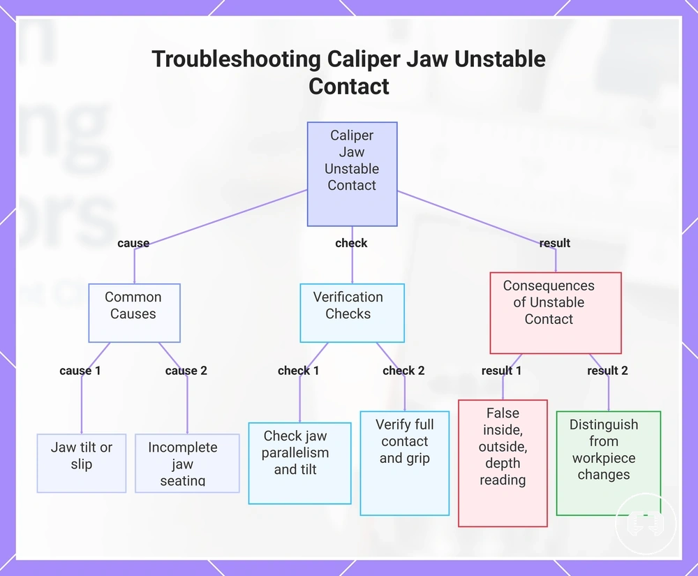
When caliper jaws are tilted, not fully seated, or slip during measurement, the reading may change even though the workpiece has not moved. Stable caliper contact depends on the inside jaws, outside jaws, or depth rod contacting the intended measuring feature correctly. Checking jaw parallelism, jaw seating, and tilt helps reduce errors caused by unstable contact.
Verify stable jaw contact before accepting the reading:
- Confirm the outside jaws are parallel to the measured surface and not affected by the part angle.
- Ensure the inside jaws are fully seated in the intended groove or internal feature.
- Check that the depth rod contacts the reference surface with proper alignment during depth measurement.
- Apply consistent grip pressure to reduce movement caused by unstable contact.
- Verify that the caliper jaws remain in full contact with the intended measuring feature throughout the measurement.
These checks help distinguish contact-related errors from changes in the workpiece itself. If jaw seating, jaw parallelism, part angle, or grip pressure changes during measurement, the result may become a false inside, outside, or depth measurement.
This chart shows the common causes of unstable caliper jaw contact, the key verification checks, and the measurement errors that result from ignoring them.
Micrometer pressure and spindle contact mistakes
When a micrometer reading changes between repeated measurements, inconsistent spindle pressure, anvil contact, or part alignment may affect the result before the scale is read. Measuring force contributes to repeatability, while poor contact between the spindle, anvil, and workpiece may produce compressed, tilted, or inconsistent readings. Consistent spindle contact supports repeatability more reliably than relying on the scale reading alone.
Use these checks to verify micrometer contact and measuring force:
- Ensure the spindle and anvil contact the workpiece with full, even contact face engagement.
- Use the ratchet or friction thimble, when provided, to help apply consistent measuring force.
- Check that the contact faces are clean before taking a measurement.
- Verify correct part seating and part alignment before closing the spindle.
- Repeat the measurement if spindle pressure or contact changes between readings.
These checks help reduce contact-related reading changes. The appropriate measuring force and contact method can vary with the micrometer design and the measurement task, so compressed, tilted, or inconsistent readings should be evaluated in that context.
Calibration, zeroing, and drift-related errors
Calibration, zeroing, and drift-related errors can make a measuring tool consistently inaccurate even when user technique appears steady. A zero reference problem usually affects the starting point of the measurement, while calibration state and drift can affect whether the tool remains trustworthy across repeated checks. The first distinction is therefore zero reference versus calibration state.
Zero checks, known standard checks, and repeated readings help separate simple correction from suspected tool bias. The flow below keeps the diagnosis focused on symptom, check, likely meaning, and next action.
| Symptom | Check | Likely meaning | Next action |
|---|---|---|---|
| Reading does not return to zero | Check the zero reference | Possible zero shift | Correct the zero reference if the tool allows it |
| Same offset appears repeatedly | Compare against a suitable known standard | Possible tool bias or calibration error | Use verification before relying on the measured result |
| Readings change across repeated checks | Review repeatability under controlled conditions | Possible drift, wear, or unstable tool condition | Consider recalibration or removal from use if verification fails |
Drift and wear may appear gradually, so one reading alone may not explain the tool condition. A known standard can help verify whether the error repeats in the same direction, while repeatability checks can show whether the tool is unstable under similar conditions. Any conclusion should remain conditional until verification confirms whether the issue is a zero shift, calibration error, or tool damage.
This section is diagnostic rather than a full calibration procedure; calibration basics explain the broader context for reference checks and recalibration decisions. A simple zero correction may be enough when only the zero reference is wrong, but suspected drift, failed verification, visible wear, or repeatability loss may require recalibration or removal from use.
When calibration error is different from user error
Calibration error is different from user error when the tool shows a repeatable bias under controlled checks instead of scattered results caused by handling or reading. A known-standard check, zero shift review, and controlled repeat measurement can help separate tool bias from an operator mistake. The key contrast is stable bias versus inconsistent readings.
Use the comparison below as a signal check, not as a certain diagnosis; calibration review should stay conditional until verified with a suitable reference or controlled repeat measurement.
| Calibration signal | User-error signal |
|---|---|
| The same wrong reading repeats in the same direction during a known-standard check. | Readings change between users, hand positions, or reading methods. |
| A zero shift remains after the zero reference is checked and the tool is used consistently. | The result changes when handling, contact, or reading interpretation changes. |
| Repeatable bias appears during controlled repeat measurement. | Scattered readings appear without a stable direction of error. |
| Verification suggests the tool may need calibration review. | User correction may reduce the error when technique or reading is adjusted. |
Surface, debris, and environmental measurement errors
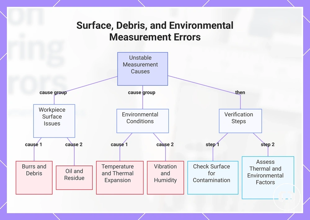
When a correct measuring technique still produces an unstable result, the workpiece surface or surrounding environmental conditions may be affecting the measurement. Burrs, debris, dirt, oil, temperature, humidity, vibration, and thermal expansion can influence contact or measurement stability even when the tool is used consistently. The likely reading outcome depends on both the workpiece surface and the environment.
Before attributing the result to the tool or the operator, verify the measurement conditions that may affect stability:
- Inspect the workpiece surface for burrs, debris, dirt, or other surface contamination that can create contact error.
- Check for oil or residue on the workpiece or measuring faces that may contribute to an unstable reading.
- Consider whether temperature differences could cause thermal expansion and a shifted dimension, depending on the material, tolerance requirement, and environment.
- Look for vibration or changing workshop conditions that may reduce repeatability during measurement.
- Note whether humidity or other environmental conditions could influence measurement stability in the current setting.
A burr, debris, or surface damage can prevent full contact with the workpiece surface and lead to contact error or an unstable reading. Temperature-related thermal expansion may contribute to a shifted dimension, while vibration or humidity can affect repeatability under certain environmental conditions. These mechanisms should be considered before concluding that calibration or user error is the primary cause of the measurement result.
This chart shows the main causes of unstable measurements from workpiece surface and environmental conditions, and the steps to verify them before blaming the tool or operator.
How to reduce repeat measurement mistakes
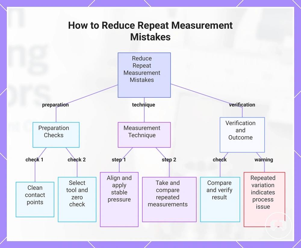
Repeat measurement mistakes can often be reduced by combining preparation, consistent technique, repeated measurement, and verification instead of relying on a single reading. A structured check sequence helps identify repeated errors before they are accepted as valid results, although the improvement may vary with the measuring tool, expected tolerance, and operator consistency. Prevention combines preparation with verification.
Use the following check sequence before accepting the measured value:
- Confirm clean contact points by checking for debris or contamination because contact quality can affect the reading.
- Select a measuring tool that is suitable for the measurement so the method matches the measurement task.
- Perform a zero check before measuring to verify the starting reference.
- Check alignment and apply stable pressure so the measuring faces contact the workpiece consistently.
- Take a repeated measurement and compare the results to assess repeatability rather than relying on a single reading.
- Compare the measured value with the expected tolerance and complete a final verification before recording the result.
Repeated measurement helps distinguish an isolated reading from recurring variation, while comparison against the expected tolerance provides context for the result. Following the proper use of measuring tools can support more consistent repeatability without replacing verification.
If repeated variation remains after the same check sequence is followed, the pattern may indicate a process issue rather than a single bad reading. Further verification can help determine whether the variation is related to the measurement process instead of an isolated measurement result.
This chart shows the structured check sequence to reduce repeat measurement mistakes, covering preparation, measurement technique, and verification steps.
Clean, align, repeat, and compare readings before trusting the result
Verify the measurement before trusting the result by confirming the conditions that most directly influence the reading. Each check helps protect the final reading by reducing the chance that a single condition affects the outcome. Use the following verification sequence before accepting a measurement.
Apply this concise checklist before recording the result:
- Confirm the tool faces and the workpiece surface are clean so debris or contamination is less likely to affect contact.
- Verify the zero state before measuring to confirm the starting reference.
- Align the measuring tool correctly so the contact points engage the intended measuring feature.
- Apply consistent measuring force to help maintain repeatability during the measurement.
- Take repeat readings and compare readings to confirm they remain reasonably consistent.
- Compare the result with another suitable reference when one is available to increase confidence before accepting the measurement.
This verification sequence helps improve confidence without implying exact certainty, and comparison with another tool or known reference is appropriate only when a suitable reference is available.
When inaccurate readings need recalibration or replacement
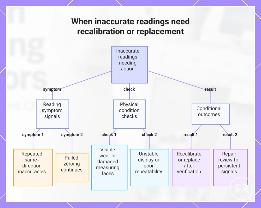
Inaccurate readings should move beyond ordinary user correction when the same symptoms continue after reasonable verification steps. Recurring tool-condition signals may indicate that technique alone is no longer the main cause, although the next action depends on verification, the tolerance requirement, and the condition of the measuring tool. Recalibration, repair, or replacement are conditional outcomes rather than automatic decisions.
Evaluate recurring symptoms before deciding on the next action:
- Check for repeated same-direction inaccurate readings after normal verification.
- Confirm whether failed zeroing continues after repeating the zero check.
- Inspect for visible wear, damaged jaws, or damaged measuring faces that may affect the reading.
- Look for an unstable display or inconsistent repeatability during repeated measurements.
- Compare the result with a known-standard check when a suitable reference is available.
- Consider whether the tolerance requirement indicates that recalibration, repair review, or replacement may be appropriate.
Persistent tool-condition signals may justify a repair review instead of further technique correction alone. When verification continues to indicate inaccurate readings, recalibrate or replace measuring tools according to the verified tool condition rather than treating replacement as the default outcome.
Ordinary measurement mistakes can often be addressed through user correction, while recurring tool-condition problems belong to calibration review or replacement decisions. For broader guidance on verification boundaries, see calibration basics, especially when failed zeroing, a failed known-standard check, or the tolerance requirement suggests that ordinary correction is no longer sufficient.
This chart shows key symptoms, physical checks, and conditional outcomes to determine whether inaccurate measuring tool readings require recalibration, repair, or replacement.