
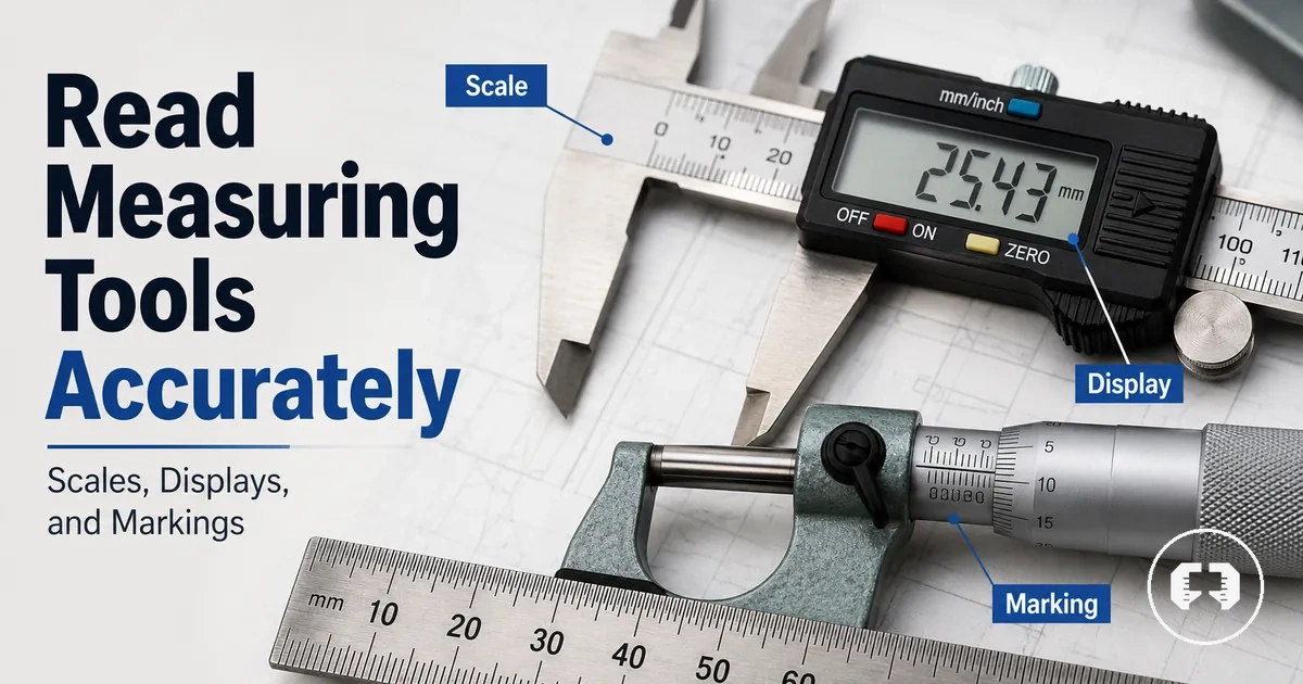
How to Read Precision Measuring Tools Accurately
Reading precision measuring tools accurately starts with checking the scale or display before recording the measurement. The value should be taken only after the zero point, unit, resolution, and visible reading condition are clear.
Precision measuring tools are measuring instruments that show a measurement through a marked scale, digital display, pointer movement, or combined scale parts. This page explains how to read the shown value; it does not prove calibration or choose a tool for a task.
Confusion often starts because a vernier, micrometer, dial indicator, and digital caliper do not present the reading value in the same way. A vernier uses a main scale and aligned line, a micrometer uses sleeve and thimble graduations, a dial indicator uses pointer movement and revolution count, and a digital caliper shows a displayed value that still depends on unit mode and zero setting.
The core reading checks organise what should be verified before the final value becomes a recorded measurement:
- Check whether the value comes from a scale, display, pointer, or combined scale parts.
- Confirm the zero point or starting reference before interpreting the reading.
- Verify the unit so the recorded measurement is not mixed between unit systems.
- Use the tool resolution to decide the last reliable digit.
- Record the value only when the visible reading appears stable enough for the tool design and condition.
The exact reading method can vary by scale layout, unit system, viewing angle, and tool condition, so the next step is to understand the scale basics before moving into digital, vernier, micrometer, and dial readings.
Measurement Scale Basics for Accurate Readings
Measurement scale basics begin with understanding how a measuring tool presents a value through its scale features. Accurate scale reading depends on interpreting the displayed value using the correct scale, unit, zero reference, and resolution before creating a recorded measurement. This section explains those attributes without verifying whether the tool itself is calibrated.
Visible scale marks, units, zero reference, and resolution determine how the shown value becomes a recorded measurement. The annotated example below highlights these features before moving into tool-specific reading methods.
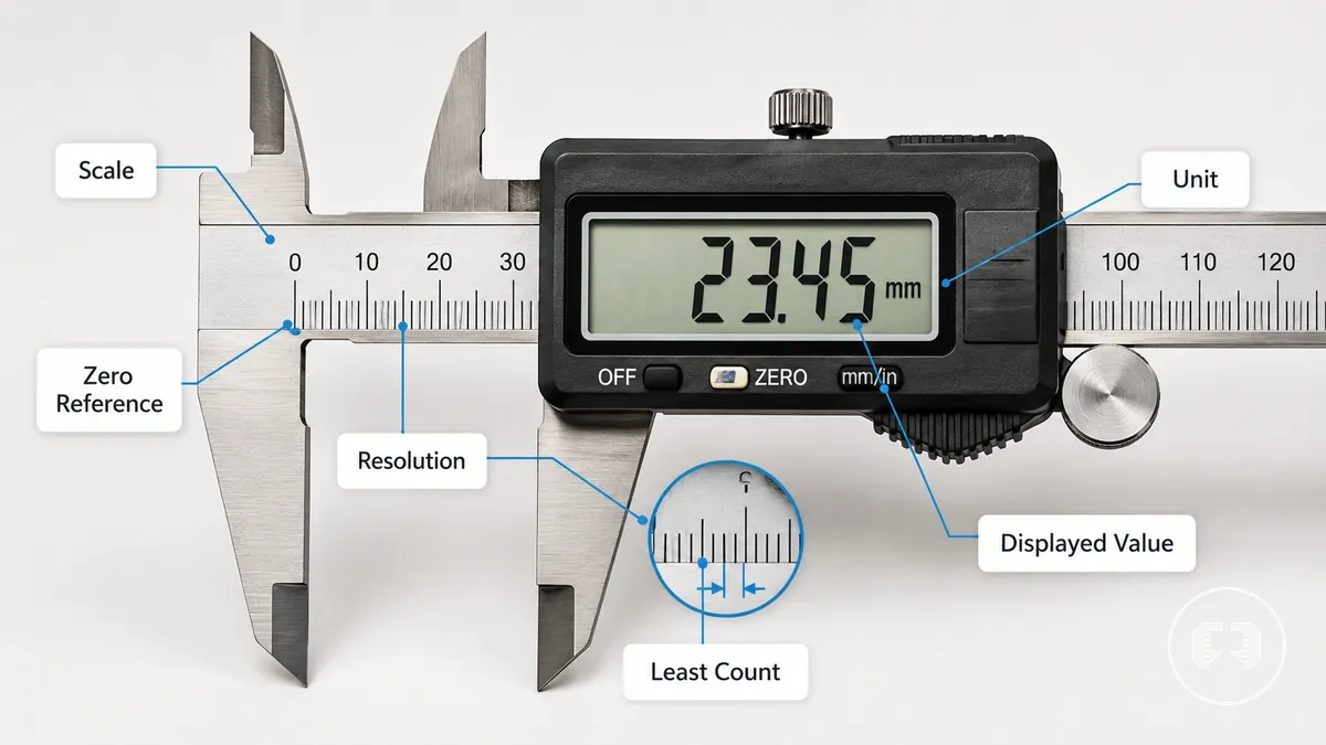
Each measurement scale feature directly affects the recorded measurement. The unit identifies the measurement system, the zero reference establishes the starting point, the least count and increment define the smallest readable division, and the displayed value is interpreted according to those scale features. This explanation complements the broader precision measuring tools guide and focuses on reading a value rather than proving calibration.
Misreading the unit, zero reference, increment, decimal place, or smallest division can produce an incorrect recorded measurement even when the displayed value appears clear. Resolution describes the smallest readable change, while resolution and tolerance basics explain why reading resolution should not be confused with tolerance. Measurement Scale Basics for Accurate Readings can be reviewed with the checklist below before recording a value.
- Confirm the measurement scale uses the intended unit.
- Check the zero reference before taking the scale reading.
- Identify the least count or smallest division between scale marks.
- Read the displayed value using the correct increment and decimal place.
- Record the final value only after confirming the scale features match the visible reading.
Units, resolution, and least count
Unit, resolution, and least count determine the smallest value that can be recorded from a measuring tool. The unit defines whether the reading is expressed in millimetres or inches, while the resolution and least count define the smallest readable increment size and available decimal place. Together, these attributes determine the smallest recorded value that the tool can represent.
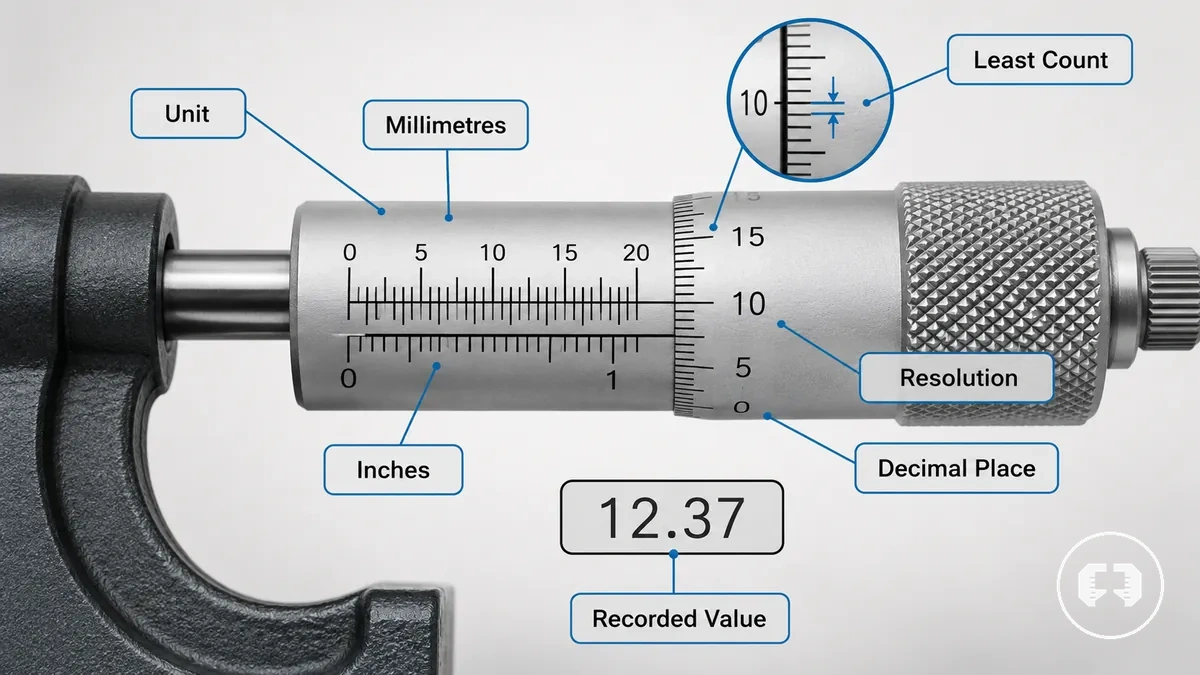
The following example clarifies how these attributes affect the recorded value. If a measuring tool is set to millimetres instead of inches, the recorded value follows that unit system, and if the least count supports only a particular increment size, the reading value should use only the available decimal place. Resolution may influence how finely a value can be read, but it does not by itself establish real-world accuracy. Do not record more digits than the tool can display or support.
Zero reference and scale starting point
The zero reference is the scale starting point for reading a measuring tool. A zero line, zero button, or datum surface establishes the reference point from which the displayed value is interpreted. When the zero reference is correctly established, the displayed value begins from the intended start point and supports a correct recorded value.
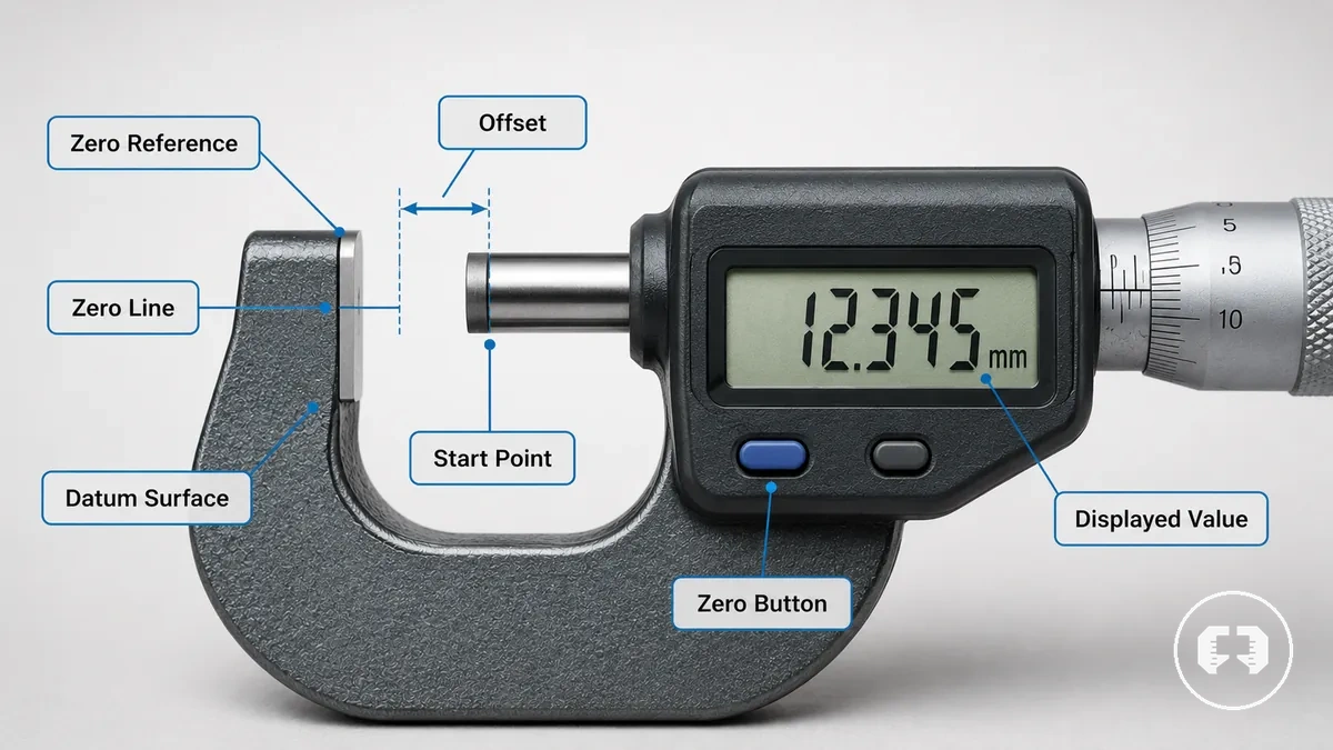
A zero offset changes the interpreted value because the reading no longer starts from the intended reference point. The offset may result from the visible zero condition, but it does not by itself indicate the overall condition of the measuring tool. The following Zero reference and scale starting point checklist verifies the visible reading start before recording a value.
- Confirm the zero line or zero mark matches the scale starting point.
- Check the zero button or digital display before reading the displayed value.
- Verify the datum surface or contact point is the intended reference point.
- Look for a visible offset before recording the displayed value.
Reading Digital Displays on Precision Measuring Tools
Read a digital display by confirming the unit mode, zero setting, stable contact, and displayed number before recording the value. A digital display removes the need to interpret scale lines, but the displayed number should still be checked for the correct unit mode, zero setting, and a stable display. A digital caliper is one example, but the same reading sequence applies to other digital precision measuring tools.
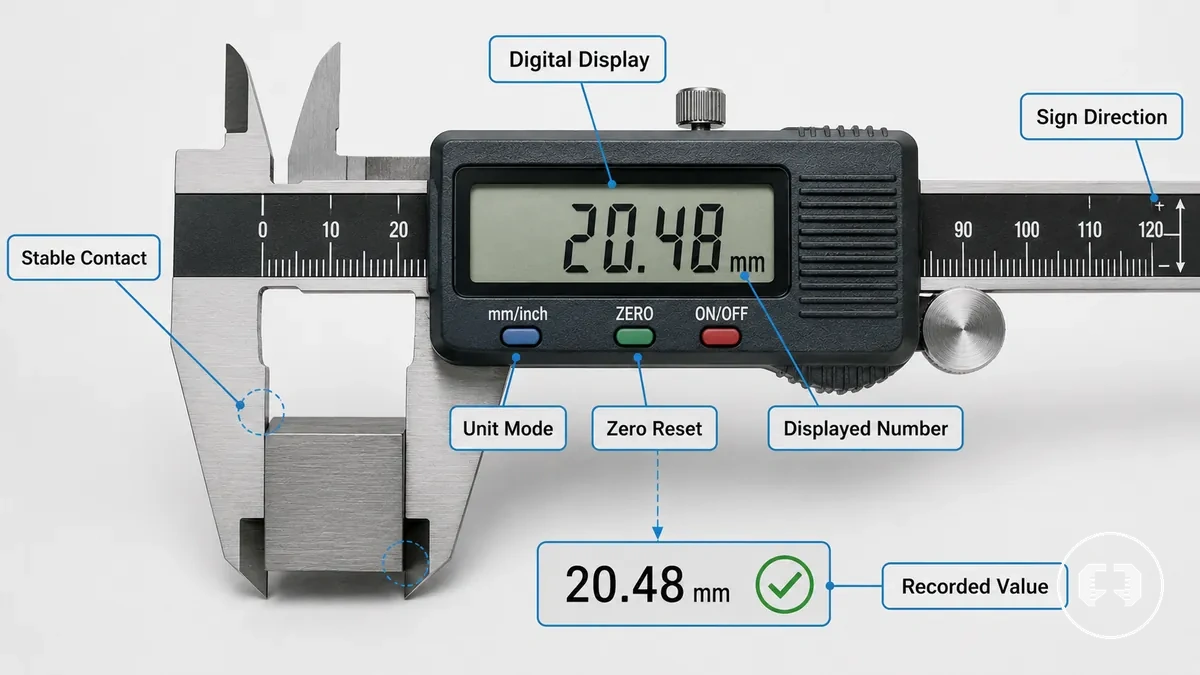
Digital digits can still be misread if the unit toggle changes, the zero reset is incorrect, or the displayed value fluctuates because stable contact has not been reached. A changing screen value or unexpected sign direction may affect the final recorded value. Follow the steps below before accepting the displayed number.
- Confirm the unit mode so the displayed number matches the intended measurement system.
- Check the zero setting or zero reset because the displayed value should begin from the intended reference point.
- Maintain stable contact and wait if the displayed number fluctuates, as movement may affect the reading.
- Verify the sign direction and displayed digits so an unexpected negative reading is not recorded.
- Record the final recorded value only after the displayed number remains stable and the display checks are complete.
Reading Digital Displays on Precision Measuring Tools requires confirming the display before recording the result. Use this quick checklist to verify the visible reading:
- Confirm the correct unit mode or unit toggle.
- Verify the zero setting or zero reset.
- Ensure the displayed number is stable.
- Check the sign direction before recording the final value.
Digital displays simplify reading by removing scale-line interpretation, but users still need to verify unit mode, zero setting, and display stability before accepting a value. For a broader comparison of digital and analog readings, remember that digital readouts simplify scale interpretation without removing the need for user checks.
Display value, unit mode, and zero setting
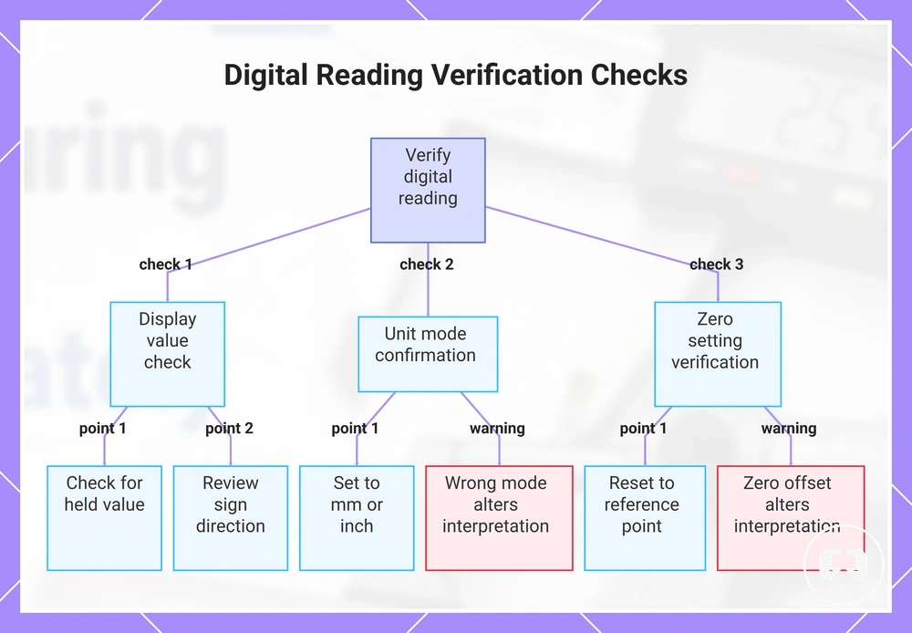
Check the display value, unit mode, and zero setting before accepting a digital reading as the recorded measurement. Confirm that the displayed digits match the intended mm or inch mode and that the zero setting is correct before recording the value.
A wrong unit mode or zero offset can change how the displayed value is interpreted even when the screen value appears clear. A held value or unexpected sign direction may also require another check before accepting the recorded measurement. Use the following checks to verify the display value, unit mode, and zero setting before recording a digital value.
- Verify the display value so the displayed digits represent the current measurement rather than an unintended held value.
- Confirm the unit mode is set to mm or inch to prevent recording the value in the wrong measurement system.
- Check the zero setting or zero reset so the displayed value starts from the intended reference point instead of an offset.
- Review the sign direction and any held value because display behavior may depend on the selected mode and current reading state.
This chart shows the three main checks to perform before recording a digital measurement: verifying the display value, confirming the unit mode, and checking the zero setting.
Stable readings before recording the value
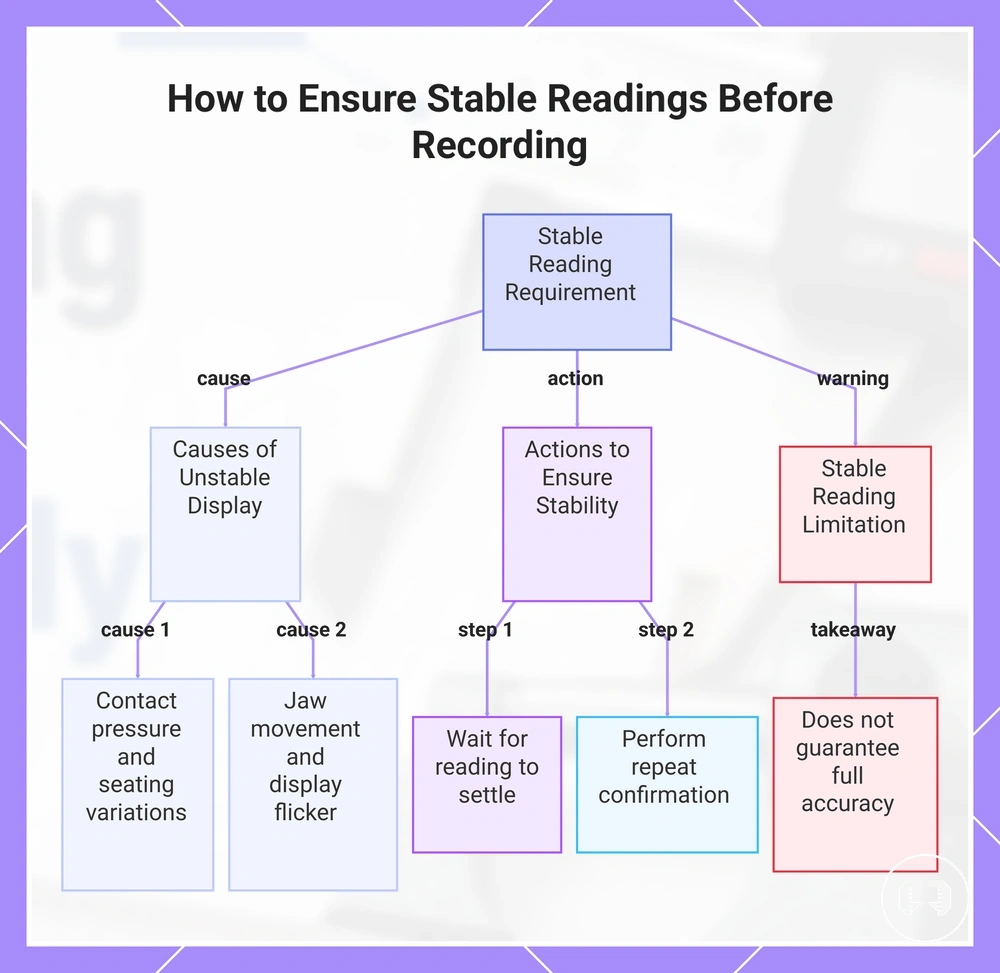
A fluctuating display should not be accepted as the recorded value. Contact pressure, jaw movement, surface seating, or display flicker can cause the displayed number to change before it settles. Wait for a stable reading before recording the value.
If the displayed number changes while jaw movement continues or the measuring surfaces have not seated evenly, the unstable value may reflect movement rather than the measurement. A repeat confirmation can help verify that the displayed number has settled under the same contact conditions, but a stable reading supports recording confidence and does not by itself prove complete measurement accuracy.
This chart explains why stable readings are necessary before recording a measurement, covering the common causes of fluctuation, recommended actions to achieve stability, and the key limitation of a stable reading.
Reading Vernier Scales
Read a vernier scale by taking the main scale value immediately before the vernier zero and adding the aligned vernier increment. The final reading is the main scale value plus the added increment determined by the least count.
The main scale provides the starting value, while the vernier zero marks where the vernier reading begins. Find the aligned line that matches a main scale mark, then use the least count to determine the added increment. If the line alignment appears unclear because the marks are difficult to distinguish or the scale is worn, check the alignment again before recording the value.
A worked example shows the method rather than a fixed result. If the main scale reads 12 units before the vernier zero and the aligned line contributes an added increment of 0.2 units according to the least count, the final reading is 12.2 units.
- Read the main scale immediately before the vernier zero to obtain the starting value.
- Locate the aligned line that matches a main scale mark.
- Use the least count to determine the added increment represented by the aligned line.
- Add the starting value and the added increment to obtain the final reading.
- Recheck the line alignment if the mark appears ambiguous before recording the value.
| Reading part | What to identify | Value added |
|---|---|---|
| Main scale | Value before the vernier zero | Starting value |
| Aligned vernier line | Line aligned with a main scale mark | Added increment from the least count |
| Final reading | Main scale plus added increment | Recorded value |
Main scale value before the vernier zero
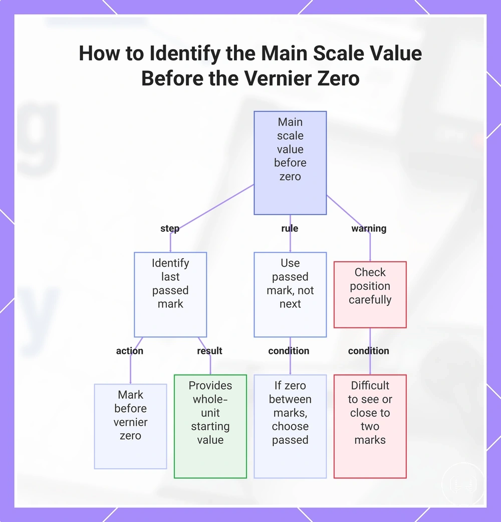
Find the main scale value by identifying the last main scale mark passed by the vernier zero. That last mark provides the whole-unit value and becomes the starting value.
The following example shows how to identify the starting value. If the vernier zero sits between two scale marks, use the passed mark rather than the next mark ahead as the main scale value. When the vernier zero is difficult to see or lies close to two marks, check its position carefully before carrying only the starting value into the next increment step.
This chart shows the steps and rules to identify the main scale value when reading a vernier scale, including a caution for careful checking.
Aligned vernier line and added increment
The aligned vernier line provides the added increment that is combined with the main scale value. Identify the line number that matches a main scale mark, then use the least count to calculate the added increment.
The following calculation combines the line number with the least count before the final addition. If the aligned vernier line is difficult to distinguish because of ambiguous alignment or a worn scale, the reading may require another careful check before accepting the increment.
Calculation example: Line number 4 × least count 0.1 units = added increment 0.4 units. Final addition: main scale value + 0.4 units.
Reading Micrometer Scales
Read a micrometer scale by combining the sleeve value, thimble value, and any vernier increment when present. The final reading comes from adding the visible values shown on the micrometer scale.
The sleeve scale provides the main visible value, including half marks when they appear. The thimble graduations provide the next value, and vernier micrometer marks may add a smaller increment on models that include them. Metric and inch layouts can use different graduations, decimal placement, and unit labels, so read the visible scale according to the marked unit.
A worked example shows how the visible values combine. If the sleeve value is 7.5 units, the thimble value is 0.23 units, and no vernier increment is present, the final reading is 7.73 units. Scale layout may vary by model, including metric and inch versions.
- Read the sleeve value from the sleeve scale, including any visible half marks.
- Read the thimble value from the aligned thimble graduations.
- Add the vernier increment if vernier micrometer marks are present.
- Combine the visible values to obtain the final reading.
- Confirm the metric or inch unit label before recording the reading.
| Micrometer part | Visible cue | Value contribution |
|---|---|---|
| Sleeve scale | Main scale and half marks | Sleeve value |
| Thimble graduations | Aligned graduation | Thimble value |
| Vernier micrometer marks | Matching vernier line when present | Vernier increment |
Sleeve value, thimble value, and vernier increment
Combine the sleeve value, thimble value, and any vernier increment to produce the summed reading. The sleeve value provides the visible base value, the thimble line contributes the next value, and the vernier line adds an optional increment when present, resulting in the summed reading.
If a sleeve half value is visible, include it before adding the thimble value. A vernier line contributes an optional increment only on micrometer scales that include vernier marks, while layouts without a vernier use only the sleeve value and thimble value. The visible sleeve, thimble, and vernier parts are combined as shown below.
Formula example: Sleeve value 7 + sleeve half value 0.5 + thimble value 0.23 + vernier increment 0 = summed reading 7.73.
Metric and inch micrometer readings
Metric and inch micrometer readings differ by scale increments and decimal placement. The unit system determines how the graduations are interpreted and how the final reading is written in the recorded unit.
A metric micrometer and an inch micrometer use different scale layouts, so the visible graduations and decimal placement guide the reading pattern. Read the value according to the marked unit system and keep the final reading in the same recorded unit.
| Unit system | Reading cue | Recording format |
|---|---|---|
| Metric micrometer | Metric graduations and decimal placement | Final reading recorded in the metric unit |
| Inch micrometer | Inch graduations and scale increments | Final reading recorded in the inch unit |
Reading Dial Indicators
Read a dial indicator by tracking pointer movement from the chosen zero. The dial reading represents movement from that reference point and is determined by the pointer position, dial graduations, direction, and revolution count.
The direction of pointer movement determines whether the displayed value increases or decreases from the chosen zero. If the dial indicator includes a small revolution dial, the revolution count contributes to the total displacement. A preload may be used before reading, and continuous movement should settle into a repeatable reading before the value is recorded.
If the dial face supports movement in both directions, clockwise and counterclockwise pointer movement may represent positive or negative movement depending on the dial layout. Interpret the displayed direction before recording the movement, while keeping setup and alignment outside the scope of reading the dial indicator.
- Confirm the chosen zero or preload before interpreting the dial reading.
- Read the pointer movement across the dial graduations to determine the movement value.
- Identify the direction of pointer movement relative to the chosen zero.
- Include the revolution count from the small dial when it is present.
- Record the value after continuous movement has settled into a repeatable reading.
Checklist:
- Chosen zero or preload confirmed
- Pointer movement matches the dial graduations
- Direction interpreted correctly
- Revolution count included when present
- Continuous movement settled before recording
This chart shows the key steps and checks for reading a dial indicator, from confirming the zero to recording the settled value.
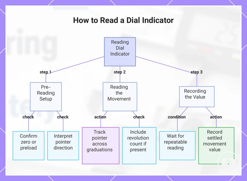
Dial graduations, pointer direction, and revolution count
Dial graduations, pointer direction, and revolution count combine to produce the movement value. The graduation size gives the value of each dial division, the travel direction shows whether movement is positive or negative, and the small revolution dial may add total displacement beyond one pointer sweep.
If the pointer travels in the positive direction for one full revolution and then continues across additional dial graduations, the revolution count and dial divisions are combined as total displacement. When the pointer direction convention or small revolution dial is unclear, check the visible dial cues again before accepting the movement value.
Worked example: graduation size × counted dial graduations + small revolution dial count = total displacement, with the sign set by pointer direction.
Continuous and balanced dial readings
Continuous pointer movement and balanced readings describe how a dial indicator displays movement around a zero-centered dial. Continuous pointer movement follows the visible change in position, while balanced readings show movement on either side of zero. The pointer position is interpreted relative to the zero-centered dial to produce the recorded value.
If the pointer moves into the plus range and then crosses into the minus range, read the movement according to the marked direction on the zero-centered dial. Back-and-forth movement with minor needle bounce may still result in a repeatable return to zero, but continued instability can affect confidence in the recorded value.
Combining Scale Parts Into the Final Measurement
The final measurement is formed by combining all visible scale parts and recording the value to the tool resolution. Read the whole units, add the increments, confirm the unit label, and keep the recorded value within the scale parts plus resolution.
Scale parts work as entity, attribute, and value checks before a number is recorded. Whole units provide the base value, increments add the smaller readable parts, decimal placement controls how the combined value is written, and the unit label defines the measurement unit. The rounding rule should follow the tool resolution so the last reliable digit is not overstated. If ambiguous marks create uncertainty, the recorded value should remain qualified or be checked again before use.
Combining Scale Parts Into the Final Measurement organizes visible scale parts into one recorded value. The same shared logic applies across digital, vernier, micrometer, and dial readings because each method turns visible cues into a combined reading that should be recorded consistently.
| Tool or scale part | Value identified | How it affects the final measurement |
|---|---|---|
| Whole-unit value | Main visible base value | Starts the final measurement |
| Added increment | Smaller readable scale part | Adds detail to the whole units |
| Unit label | Marked measurement unit | Controls decimal placement and recorded unit |
| Rounding condition | Tool resolution or ambiguous marks | Limits the last reliable digit |
This shared reading logic supports using measuring tools correctly because the recorded value should come from visible scale parts, unit control, and the tool resolution rather than from guessed extra digits.
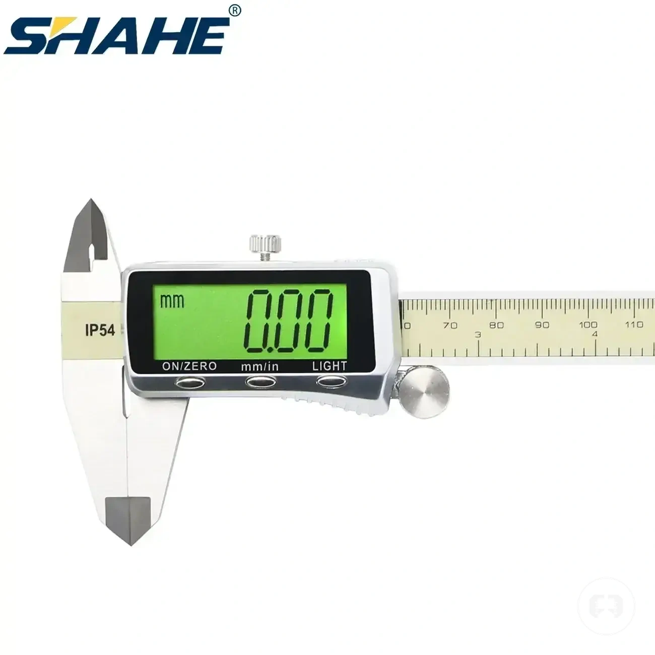
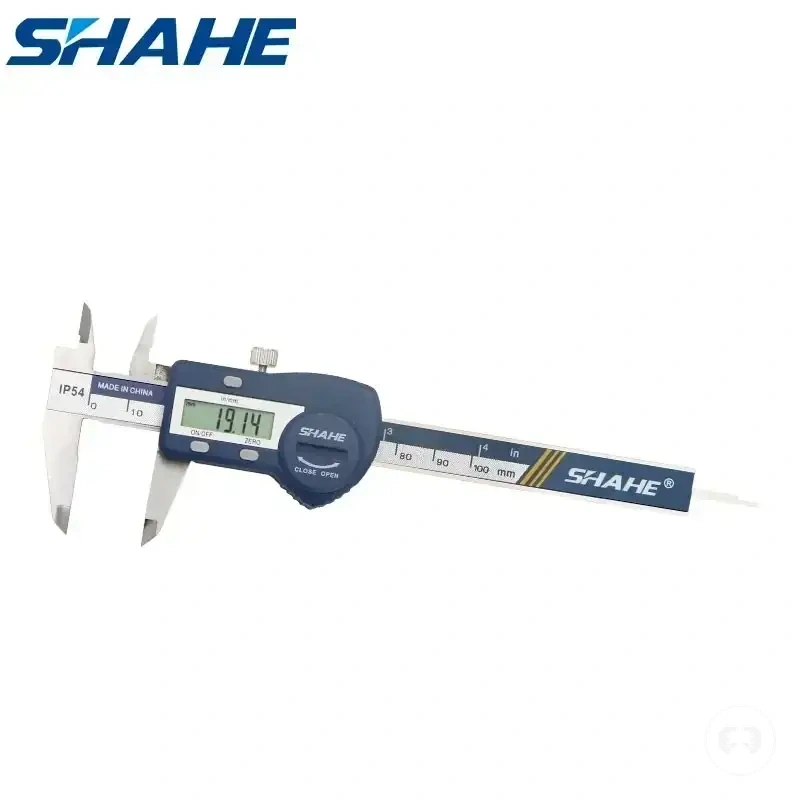
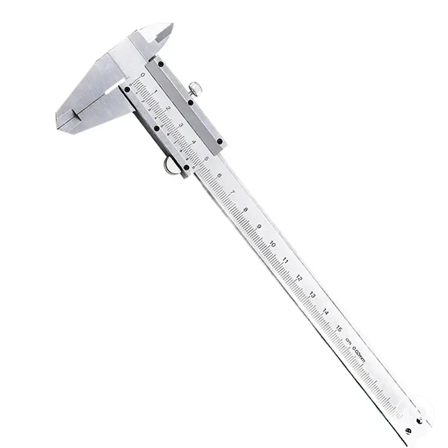
Easier-to-read examples may help when the marks, display, or pointer position are difficult to interpret, but the same recording criteria still apply. Compare the visible value, unit label, and resolution before accepting the final measurement.
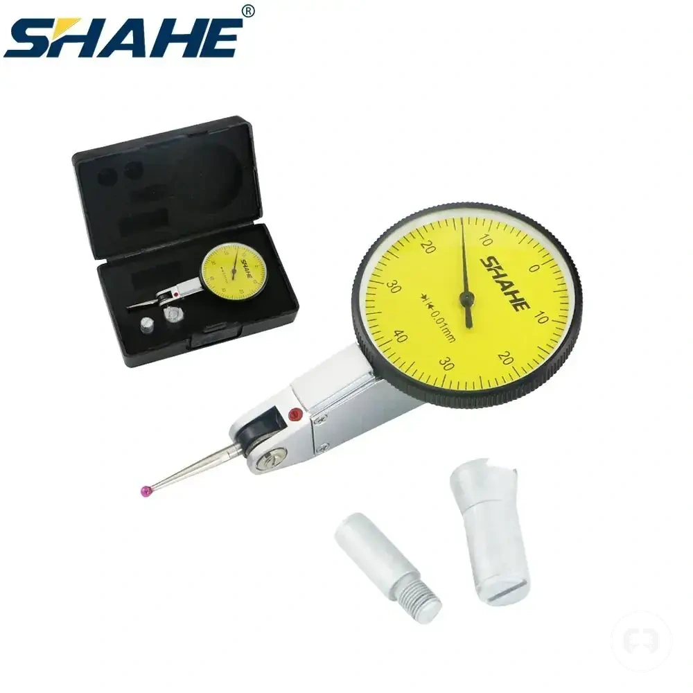
The products below are useful examples for comparing available options. Before buying, check that the compatibility criteria, key features, and product details match your needs.

Whole units, decimal increments, and final value
Combine the whole units and decimal increments to produce one final value. Start with the base unit, add the fractional increment, and record the final number with the correct unit label so the final value reflects the combined reading.
If a decimal increment is clearly identified, combine it with the base unit before recording the reading. The following calculation shows which values are being combined: Base unit 12 + fractional increment 0.3 = final number 12.3. If the decimal increment or unit label is unclear because a mark is ambiguous, the recorded total may require confirmation before the final value is accepted with the stated unit label.
Rounding the reading to the tool resolution
Rounding should match the tool resolution or least count that the scale can reasonably display or mark. The recorded value should stop at the last reliable digit.
An uncertain mark can make the final digit unclear, especially when the pointer, line, or display sits between readable positions. Rounding protects the clarity of the recorded value, but it does not improve the physical accuracy of the measurement. Use the checklist below to keep the recording format consistent.
- Match rounding to the tool resolution or least count.
- Record only to the last reliable digit.
- Qualify or recheck the value when an uncertain mark affects the decimal place.
- Use a consistent recording format for repeated readings from the same tool.
- Use resolution and tolerance basics to separate recording precision from tolerance decisions.
Reading Errors That Distort Precision Measurements
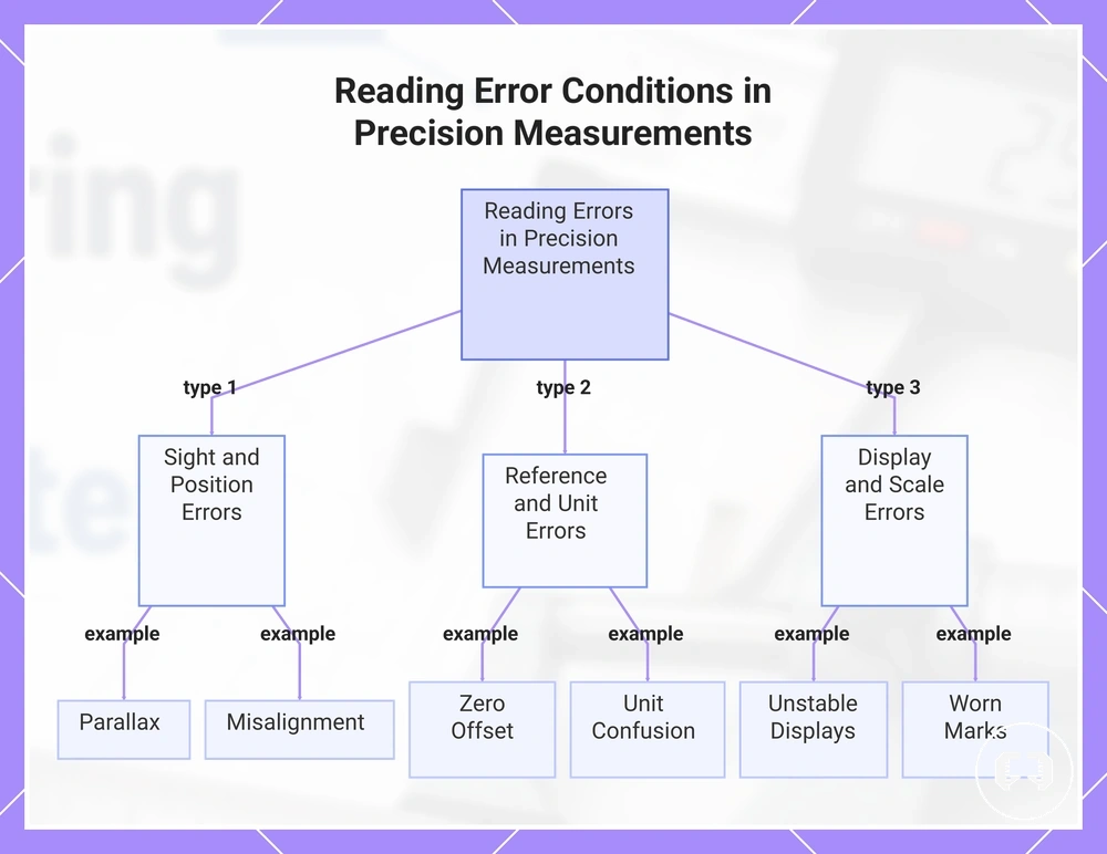
Reading errors occur when the recorded value does not match the scale, display, zero reference, or viewing condition. These reading errors can distort precision measurements because the recorded value no longer reflects what the scale or display is intended to show under the current viewing condition.
Parallax can shift the apparent line position when the viewing angle changes, misalignment can place the reading against the wrong reference mark, and zero offset can change the starting point before measurement begins. Unit confusion, rounding errors, unstable displays, and worn or unclear marks can also change the recorded value. The resulting measurement effect depends on which reading condition is present.
Reading Errors That Distort Precision Measurements can be checked by comparing the visible reading conditions with the recorded value. The checklist below helps identify which reading condition may have changed the final measurement.
- Parallax: A changed viewing angle can shift the apparent line position and may produce a misread value.
- Misalignment: Reading from the wrong reference mark can change the recorded value.
- Zero offset: A visible zero difference before measurement may shift the final reading.
- Unit confusion: An incorrect unit label can change how the recorded value is interpreted.
- Unstable displays: Flickering digits may require a repeat reading before recording the value.
- Worn or unclear marks: Difficult-to-read graduations may require a qualified reading or another visual check.
- Rounding errors: Recording beyond the readable precision can change the reported measurement value.
Small reading mistakes can change a recorded value without necessarily indicating a broader problem with the measuring tool. For broader guidance on reading mistakes and measurement errors, continue to the dedicated errors page.
This chart shows the common reading error conditions that can distort precision measurements, grouped into three categories for easy identification and checking.
Parallax, line alignment, and viewing angle
Parallax occurs when the viewing angle changes and the visible reading shifts from the true scale alignment. A change in eye position can make the apparent mark or pointer position appear different, so line alignment should be judged from an aligned viewing position to reduce visual reading distortion.
For example, a pointer may appear to match one scale line when viewed from the side but align with a different mark when viewed directly in front of the scale. On a mirrored scale, matching the pointer with its reflection can help indicate correct eye position, while scales without a mirrored scale rely on careful aligned viewing as the control.
Zero offset, unit confusion, and unstable readings
Zero offset, unit confusion, and unstable readings can create an incorrect recorded measurement before the value is recorded. A nonzero start changes the reference point, a wrong unit mode switches between mm and inch, and a fluctuating value can reduce confidence in the recorded measurement.
These conditions usually appear before recording and should be checked locally rather than treated as proof of a broader measurement problem. A nonzero start, mm or inch mismatch, unexpected sign direction, or unstable value may indicate a reading error, so use the checklist below before accepting the recorded value.
- Zero offset: A nonzero start may shift the recorded measurement from the intended reference.
- Unit confusion: Confirm that the display is set to mm or inch to avoid recording the wrong unit mode.
- Unstable readings: A fluctuating value may require a repeat-check condition before recording.
- Sign direction: Check that the displayed positive or negative sign matches the expected reading direction.
- Repeat-check condition: Repeat the reading if the nonzero start, wrong unit mode, fluctuating value, or sign direction remains uncertain.