Precision Measuring Tool Types by Measurement Role
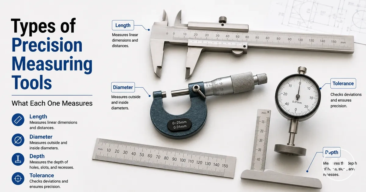
Precision measuring tools are measuring instruments grouped by the measurement role they serve, such as reading a dimension, checking a reference, or observing small movement. Each tool type connects a measurement target to a reference surface, a reading method, and realistic measurement limits. Calipers, micrometers, gauges, and indicators differ because they are built around different contact points, ranges, and ways of interpreting a result. Tool type follows measurement role.
The right tool type depends on the task, material, access, range, tolerance need, setup, and tool condition. A measuring device may be suitable for one feature but less suitable for another when the reference method or reading method changes. This page stays focused on type explanation rather than buying, calibration, or full usage guidance. For the broader category context, use the precision measuring tools hub before moving into grouped tool roles.
A shaft diameter, a slot depth, a surface height, and a runout check do not ask the same question from a measuring tool. Each situation changes the measurement target, the reference surface, and the way the reading is taken. The sections below group precision tools by the role they perform so the tool family can be understood before individual instruments are compared.
How Precision Measuring Tools Are Grouped
How precision measuring tools are grouped is based on measurement function rather than brand or product range. The grouping separates tool families according to the measurement target, reference method, and the way a result is obtained. This classification explains how tools relate to one another, while the meaning of precision measuring tools explains what they are in a broader sense. Measurement function is the organizing principle.
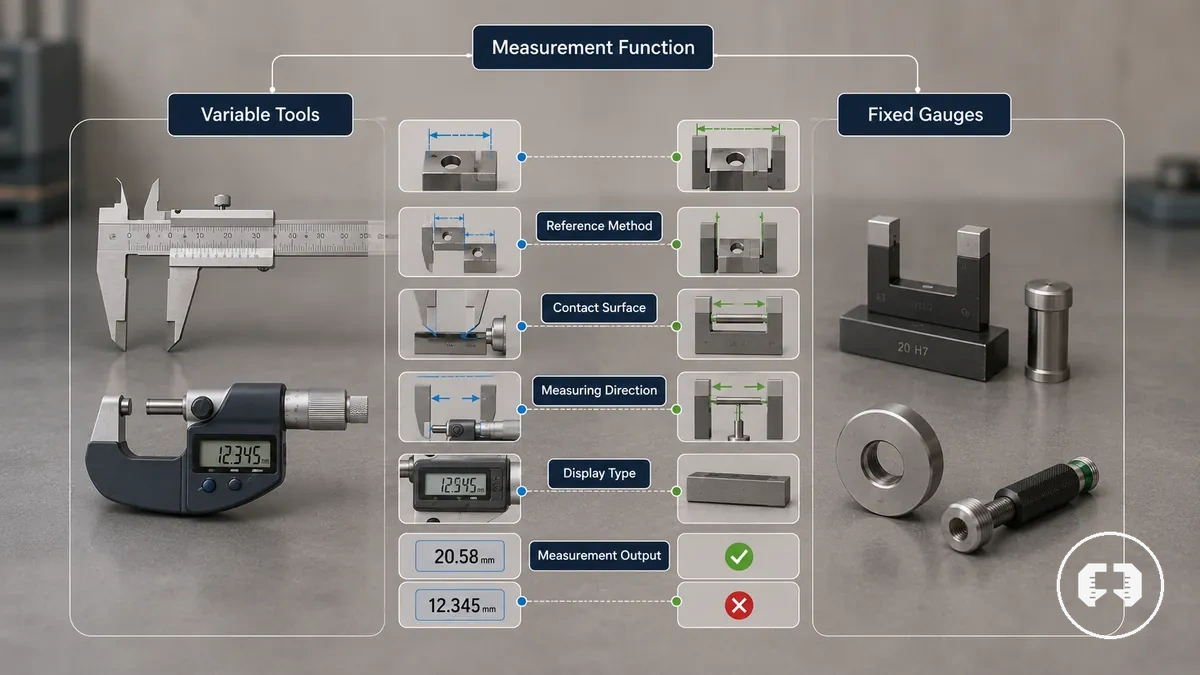
Precision measuring tools are commonly classified into variable measuring tools and fixed reference gauges. Variable measuring tools provide a measurement output for a dimension, while fixed reference gauges are used to check a reference value or fit condition without necessarily displaying a numerical reading. Tool families may also be classified by contact surface, measuring direction, display type, and reading method because these attributes help describe how a measurement is taken. This distinction separates variable reading from fixed checking.
How Precision Measuring Tools Are Grouped depends first on the measurement target and reference method, making the classification easier to interpret before comparing individual tool families. This section focuses on classification rather than the broader meaning of precision measuring tools or later tool-specific guidance.
| Grouping basis | What it separates | Example tool families | Why it matters |
|---|---|---|---|
| Measurement function | Measurement target and intended role | Calipers, micrometers, gauges, indicators | Clarifies the purpose of each tool family |
| Reading style | Variable reading versus fixed checking | Variable measuring tools, fixed reference gauges | Distinguishes measured output from verification |
| Reference method | Direct measurement or comparison against a reference | Measuring instruments, reference gauges | Helps explain how results are interpreted |
| Contact direction | Contact surface and measuring direction | External, internal, depth, and comparison tool families | May influence suitability depending on access and measurement features |
Variable measuring tools and fixed reference gauges
Variable measuring tools and fixed reference gauges are distinguished by the type of result they provide. Variable measuring tools read a dimension across a usable range, while fixed reference gauges compare a feature against a reference value for verification. Calipers, micrometers, and indicators are examples of variable measuring tools, while gauge blocks, plug gauges, and ring gauges are examples of fixed reference gauges. The distinction is between reading a dimension and checking a reference.
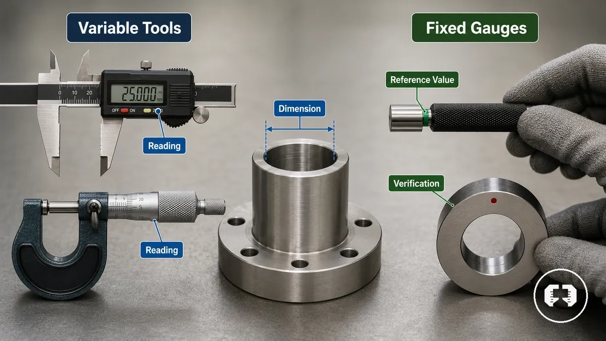
Variable measuring tools and fixed reference gauges organize this comparison by separating continuous measurement from reference checking.
| Variable measuring tools | Fixed reference gauges |
|---|---|
| Purpose: Read a dimension | Purpose: Verify against a reference value |
| Output: Variable reading | Output: Reference or go/no-go style verification |
| Examples: Calipers, micrometers, indicators | Examples: Gauge blocks, plug gauges, ring gauges |
A shaft diameter, hole, or similar feature may first be measured with a caliper or micrometer to obtain a variable reading, then checked with a fixed reference gauge when verification against a reference value is needed. Whether a fixed reference gauge confirms suitability depends on the selected reference value, tolerance, and the condition of the feature being checked, allowing the same part feature to be either measured or verified.
Measurement target, contact point, and reading method
Measurement target, contact point, and reading method define how a measuring tool interacts with a workpiece feature and presents a result. The measurement target identifies the feature being evaluated, the contact point identifies where the tool touches the workpiece or reference surface, and the reading method describes how the result is viewed. Together, these three relationships connect the feature, the contact, and the reading.
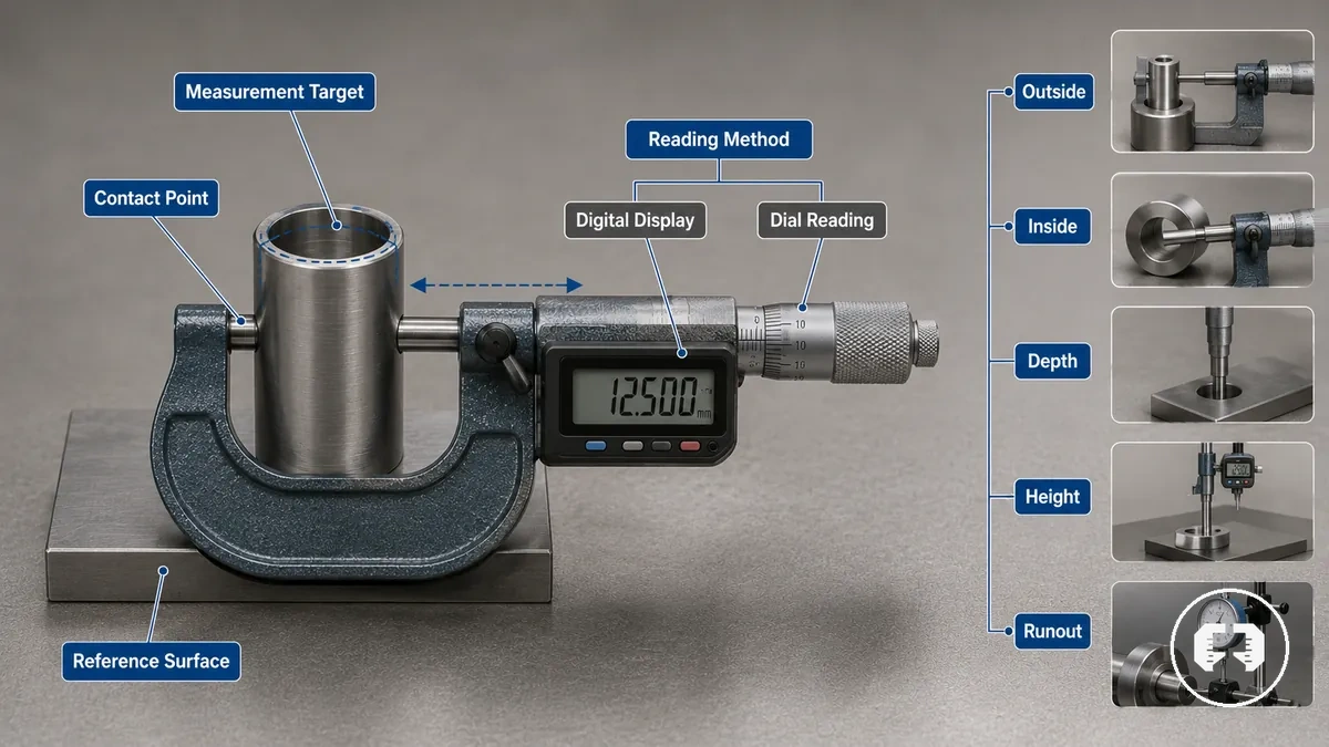
Measurement target, contact point, and reading method help organize how tool types are understood before comparing individual instruments. A tool family may share a reading method while serving different measurement roles, so the examples below focus on the relationship between the feature, the contact point, and the result. For clarification of how reading quality is evaluated, see measurement quality terms.
- Outside: The measurement target is an external feature, the contact point touches outer surfaces, and the reading method may use direct reading, dial reading, or a digital display.
- Inside: The measurement target is an internal feature, the contact point reaches inside the workpiece, and the reading method may vary with the tool design.
- Depth: The measurement target is the bottom of a feature, the contact point references the surface, and the result is shown through a direct, dial, or digital reading.
- Height: The measurement target is vertical position, the contact point references a surface, and the reading indicates the measured height.
- Runout and alignment: The measurement target is relative movement or position, the contact point follows the feature, and dial reading commonly displays the observed movement.
- Fixed-reference checking: The measurement target is compared with a reference value, the contact point checks the feature, and the result is verification rather than a continuous measurement reading.
Calipers for Inside, Outside, Step, and Depth Measurements
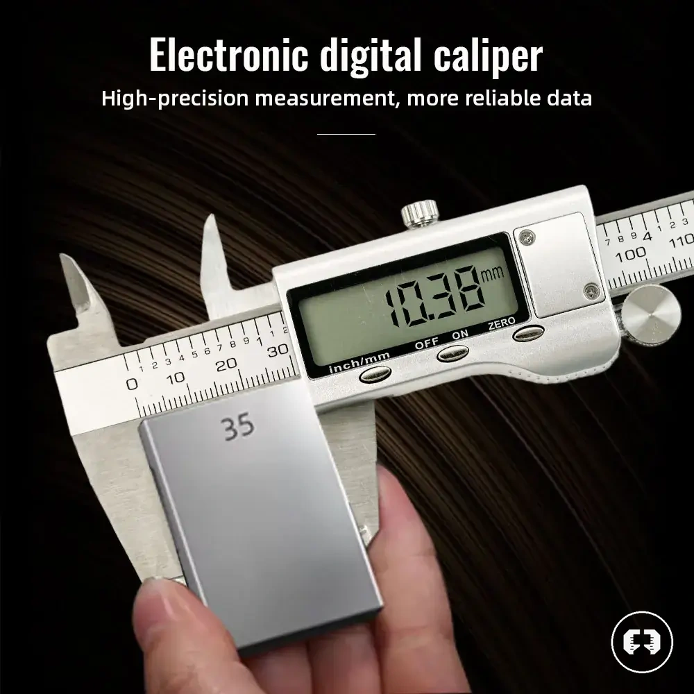
Calipers are precision measuring tools designed to measure multiple dimension types on a workpiece using different contact features. Calipers vary by jaw, probe, scale, display, and measurement contact, allowing one instrument to evaluate a range of common part features. Outside jaws, inside jaws, a depth rod, and a step face each serve a distinct measurement role. Together, they support outside, inside, step, and depth measurements.
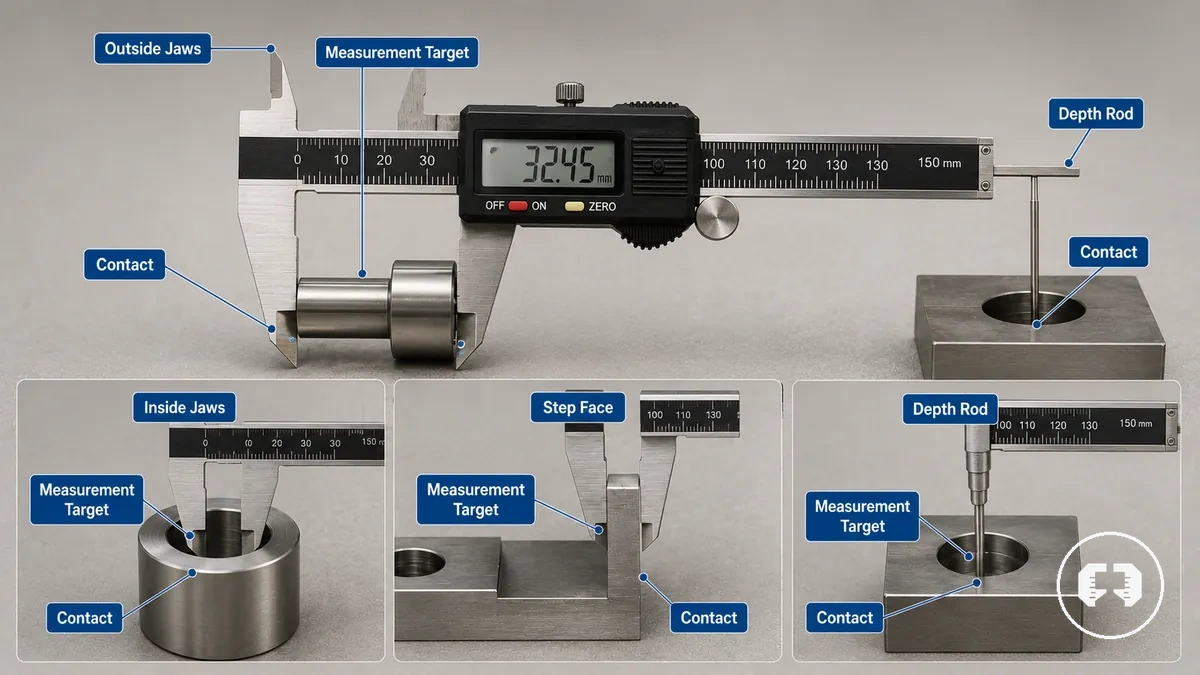
A shaft, hole, recess, or shoulder can often be measured with the same pair of calipers by changing which contact feature touches the workpiece. Outside jaws contact external surfaces, inside jaws reach internal features, and the depth rod references a surface while extending into a recess or hole. Step measurement uses the step face to compare two aligned reference surfaces. Each measurement role is defined by the contact between the caliper feature and the workpiece.
Calipers have practical limitations because measurement results can vary with contact, feature access, reading technique, and the required tolerance. Range, resolution, and repeatability describe different measurement attributes and should not be interpreted as the same characteristic. A caliper may be suitable for many dimensional checks, but tolerance suitability depends on the feature, measurement conditions, and application requirements.
The table below summarizes how caliper features relate to measurement targets and contact conditions. It provides a compact overview of the main measurement roles without becoming a usage guide.
| Caliper feature | Measurement target | Contact condition | Practical limitation |
|---|---|---|---|
| Outside jaws | Outside dimension | Contacts external surfaces | Access and contact quality may influence repeatability |
| Inside jaws | Internal diameter or opening | Contacts internal surfaces | Limited by internal access and feature geometry |
| Depth rod | Hole or recess depth | References the surface while the rod extends into the feature | Requires stable reference surface contact |
| Step face | Step measurement | Contacts two offset reference surfaces | May be less suitable when feature alignment or access is restricted |
Digital, dial, and vernier caliper readings
Digital, dial, and vernier caliper readings differ in how a measurement is displayed and interpreted. A digital caliper presents the reading on a digital display, a dial caliper uses a pointer on a dial scale, and a vernier caliper requires manual interpretation of the vernier scale. These are the three primary caliper reading formats.
When measurements are taken under different lighting, viewing angles, or working conditions, the reading format can affect visibility, reading skill, interpretation, and error risk. A digital caliper may simplify reading through its display but depends on a battery, while a dial caliper and vernier caliper rely on mechanical scales without battery dependence. Regardless of the reading format, verification remains important because repeatability also depends on contact, setup, and measurement conditions. Broader differences between digital and analog measuring tools belong outside this caliper-specific comparison.
The comparison below summarizes how each reading format presents a measurement and the main local considerations.
| Caliper reading format | How the reading appears | Main dependency | Local caution |
|---|---|---|---|
| Digital caliper | Digital display | Battery and display visibility | Verification may still be needed for consistent readings |
| Dial caliper | Pointer on a dial scale | Dial scale interpretation | Reading clarity may vary with viewing angle |
| Vernier caliper | Vernier scale | Manual reading skill | Scale interpretation may require more attention and verification |
Micrometers for Small Dimensions and Tighter Measurement Control
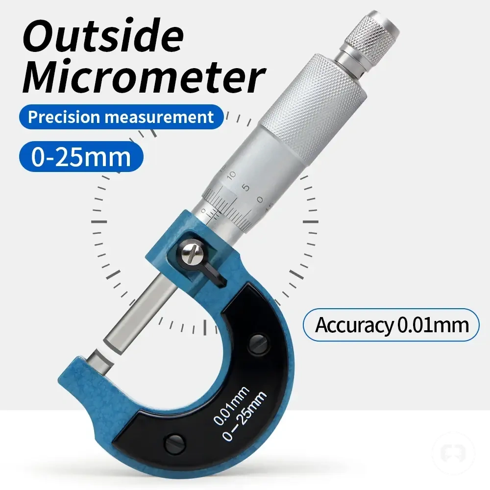
Micrometers are precision measuring tools used for measuring small dimensions where tighter measurement control may be appropriate than with broader general-purpose tools. Their suitability depends on contact geometry, measuring range, resolution, technique, and the required tolerance rather than on the tool alone. The spindle, anvil, thimble, and ratchet each contribute to controlled measurement contact and reading. Whether a micrometer provides tighter measurement control depends on calibration, handling, tool condition, and the measurement task.
When measuring a shaft diameter or the thickness of a thin part, a micrometer can provide more controlled contact than a broader caliper-style measurement. The spindle advances toward the anvil while the thimble controls movement, and the ratchet or friction control can help apply more consistent measuring force. Micrometers are available for outside measurement, inside measurement, and depth measurement, with each design matching a different feature type. Contact geometry determines how the measuring faces engage the workpiece.
Micrometers are generally most suitable when the measuring range, resolution, and contact geometry match the feature being inspected. Their components support controlled measurement, but measurement confidence still depends on calibration, handling, tool condition, and the required tolerance. A micrometer should be selected according to the feature and measurement objective rather than assumed to suit every application. Technique and tool condition remain important limits on measurement results.
The comparison below summarizes the main micrometer attributes and how each contributes to measurement control. It focuses on functional characteristics rather than product variants or calibration procedures.
| Micrometer attribute | What it controls | Condition that affects it | Measurement implication |
|---|---|---|---|
| Spindle and anvil | Contact geometry | Alignment and workpiece contact | Supports controlled measurement of small dimensions |
| Thimble | Reading adjustment | Operator technique | Influences consistent measurement control |
| Ratchet or friction control | Measuring force | Handling method | May improve repeatability when used consistently |
| Measuring range and resolution | Measurement suitability | Required tolerance and feature size | Selection depends on the measurement application |
Outside, inside, and depth micrometers
Outside, inside, and depth micrometers are distinguished by the dimension direction they are designed to contact and measure. Each subtype changes the contact faces, reference surfaces, measuring range, and usable measurement target while remaining within the same micrometer family. The distinction is based on outside, inside, and depth measurement.
When a part feature changes from an external diameter to an internal opening or a depth feature, the appropriate micrometer subtype may also change. Measuring range, feature access, and contact geometry influence whether a subtype is suitable for the measurement task. The selected subtype should match the part feature and its dimension direction.
The comparison below summarizes how each micrometer subtype relates to contact direction and measurement role.
| Micrometer subtype | Contact direction | Suitable feature | Main limitation |
|---|---|---|---|
| Outside micrometer | External measurement between contact faces | External diameter or part thickness | Measuring range and feature size may limit suitability |
| Inside micrometer | Internal measurement against contact faces | Internal dimension or bore | Access and feature geometry may affect use |
| Depth micrometer | Depth measurement from a reference surface | Hole, slot, recess, or other depth feature | Requires a stable reference surface and suitable measuring range |
Calipers and Micrometers in Different Measurement Situations
Calipers and micrometers should be selected according to the measurement situation rather than by overall superiority. Dimension type, tolerance need, accessibility, repeatability, contact control, resolution, and measuring range each influence tool choice. Calipers and micrometers serve different measurement contexts, so the appropriate tool changes with the feature being measured. Neither tool is the preferred option for every measurement situation.
When a quick check across multiple feature types is needed, calipers can provide broader versatility through outside, inside, and depth measurement capabilities. When an outside dimension requires more controlled contact and repeatability, a micrometer may be more suitable if its measuring range matches the feature. Part access, contact pressure, and error sensitivity influence the result, making these the primary comparison criteria.
The main trade-off is between broader measurement versatility and more controlled outside measurement. Calipers often support faster checks across different feature types, while micrometers may be preferred for tighter controlled outside measurements when the measurement context and tolerance need justify their use. Tool selection should follow the measurement situation rather than a universal ranking.
| Measurement situation | Caliper fit | Micrometer fit | Decision cue |
|---|---|---|---|
| Broad outside checks | Well suited for quick dimensional checks across a wider range | May be suitable when greater contact control is needed | Balance speed with tolerance need |
| Tight outside dimensions | May provide an initial measurement | Often suitable when contact control and repeatability are priorities | Consider tolerance, contact control, and resolution |
| Inside dimensions | Supports internal measurements with inside jaws | May be suitable when an inside micrometer matches the feature | Match the tool to accessibility and dimension type |
| Depth checks | Supports depth measurements with a depth rod | May be suitable when a depth micrometer matches the application | Choose according to reference surface and feature depth |
| Restricted access | Suitability depends on jaw access and feature geometry | Suitability depends on measuring range and contact geometry | Evaluate accessibility before selecting the tool |
Dial Indicators for Runout, Alignment, and Small Movement Checks
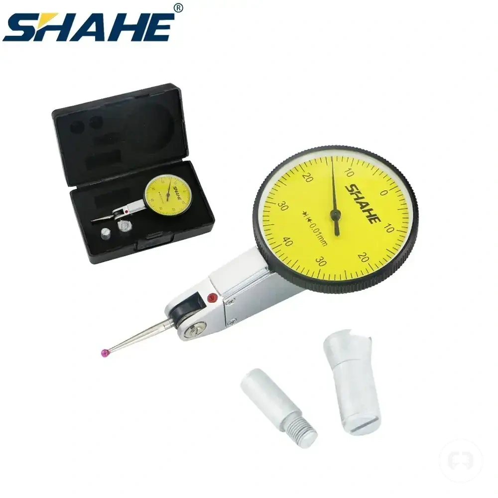
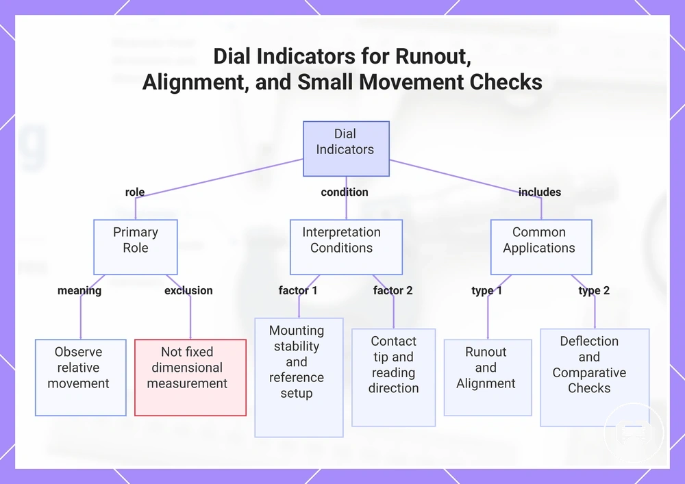
Dial indicators are measuring instruments that show relative movement against a reference setup rather than providing a fixed dimensional measurement alone. A plunger transfers movement from the contact tip to the indicator reading, allowing small movement to be observed. Reading direction, mounting stability, and the reference surface influence how the indicator reading is interpreted. Their primary role is to observe relative movement.
When a rotating part, reference surface, or supported component is compared against a fixed reference, a dial indicator can reveal movement or variation that may not be obvious by direct observation. The contact tip follows the measured surface while the plunger responds to changes in position, producing an indicator reading for comparative measurement. Interpretation remains conditional because mounting stability, contact tip position, reading direction, and the reference setup affect the observed result. Common applications include runout, alignment, deflection, and comparative measurement.
Dial indicators are intended for observing movement and variation rather than replacing direct dimensional measurement. They can support comparison between reference positions, but the meaning of a reading depends on the reference setup and measurement conditions. Detailed setup procedures, machining methods, calibration, and diagnostic workflows remain outside the scope of this section.
The examples below show common movement checks and the reference relationship each depends on.
- Runout: Compares a rotating part against a fixed reference setup to observe relative movement.
- Alignment: Compares component position relative to a reference surface or reference setup.
- Deflection: Observes small movement relative to a stable mounting reference under changing conditions.
- Comparative measurement: Compares one position or surface against another using the same reference setup.
- Height variation: Observes changes relative to a reference surface when comparing nearby points.
This chart shows the primary role of dial indicators, the conditions affecting their interpretation, and their common applications for movement checks.
Dial indicators and dial test indicators
Dial indicators and dial test indicators both indicate small movement, but they differ in contact geometry. A dial indicator uses plunger travel with straight movement, while a dial test indicator uses lever contact that approaches the workpiece from an access angle. Contact geometry is the primary distinction between the two indicator types.
When an alignment check involves restricted access or an angled contact position, a dial test indicator may provide an access advantage because of its lever contact. A dial indicator is often suitable where straight plunger travel aligns with the reference setup and setup direction. Differences in sensitivity remain conditional because access angle, workpiece geometry, and setup direction influence the measurement context. The comparison below is limited to access and movement style.
The table below summarizes the local distinction between the two indicator forms.
| Indicator type | Contact movement | Access advantage | Local caution |
|---|---|---|---|
| Dial indicator | Straight plunger travel | Often suitable when direct access aligns with the reference setup | Setup direction influences the indicator reading |
| Dial test indicator | Lever contact | May be advantageous where the access angle is restricted | Sensitivity depends on workpiece geometry, contact angle, and setup direction |
Depth Gauges and Height Gauges for Vertical Reference Measurements
Depth gauges and height gauges measure different vertical reference relationships rather than performing the same measurement. A depth gauge measures downward from a top surface to determine features such as hole depth or recess depth, while a height gauge measures upward from a surface reference, often a surface plate, to establish layout height or other vertical dimensions. Base contact, probe direction, and the selected surface reference determine how each tool is applied. The distinction is defined by the reference relationship rather than the measurement direction alone.
When a measurement begins from the top surface of a workpiece, a depth gauge uses base contact while the probe extends toward the bottom feature to measure hole depth or recess depth. When a measurement begins from a surface plate reference, a height gauge uses vertical travel to establish or compare layout height. Practical measurement confidence may depend on base contact, surface stability, probe direction, access, measurement range, and reading conditions. These reference relationships distinguish depth and height measurement use cases.
Depth measurement and height measurement are not interchangeable because they rely on different vertical references. A depth gauge measures downward from a top reference, whereas a height gauge measures upward from a surface reference. This comparison is limited to reference relationships and does not extend into material compatibility or complete layout workflows.
| Vertical measurement need | Depth gauge role | Height gauge role | Reference condition |
|---|---|---|---|
| Hole depth | Measures downward from the top surface | Not typically used for this measurement | Base contact on the top surface |
| Recess depth | Measures downward probe travel into the recess | May not match the required reference relationship | Stable top-surface reference |
| Layout height | Not intended for upward layout measurement | Measures vertical travel from a surface plate reference | Surface plate or another stable surface reference |
| General vertical reference | Uses downward probe direction | Uses upward measurement from a surface reference | Reading may depend on stability, access, and measurement range |
Depth gauges for recesses, grooves, slots, and holes
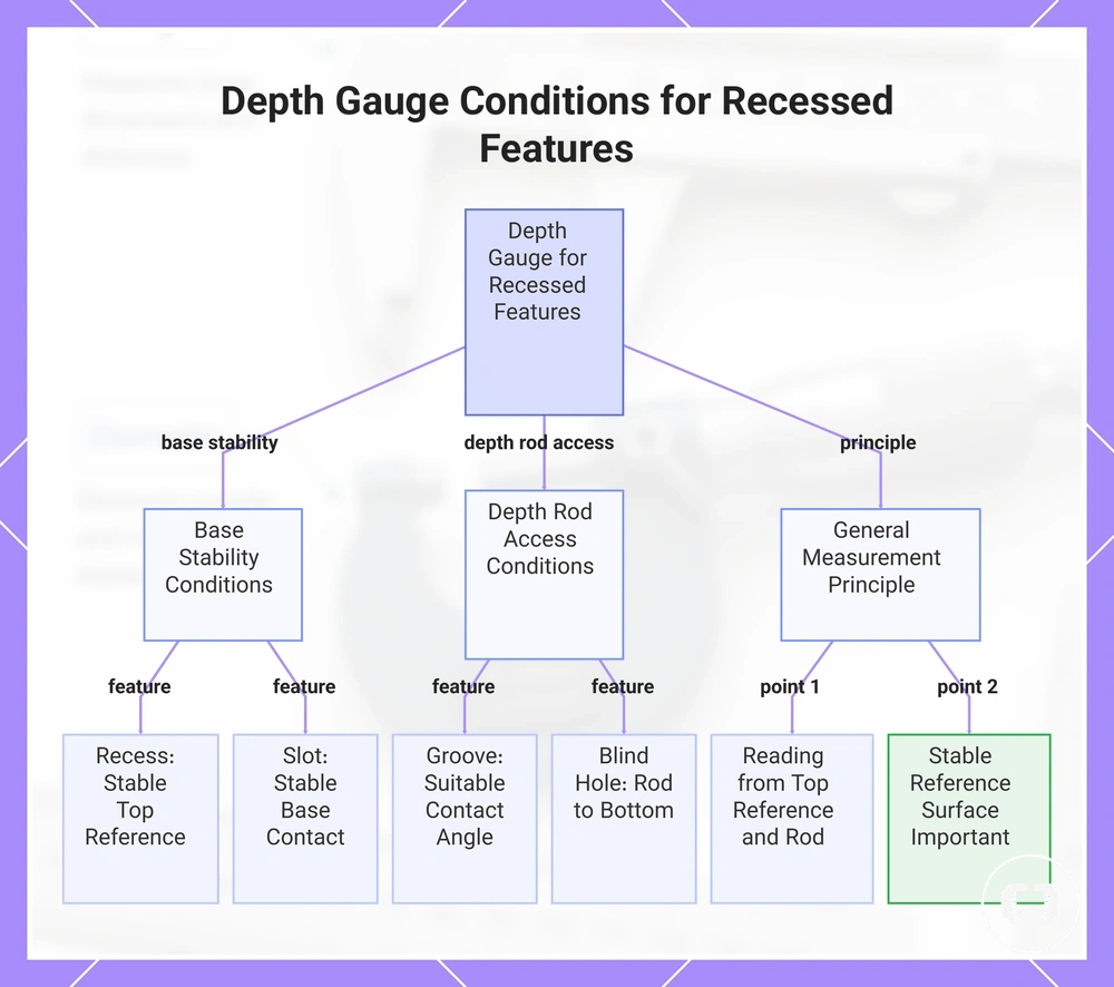
Depth gauges are precision measuring tools designed for recessed features where depth measurement depends on a stable top reference and a depth rod reaching the lower feature. The reading is determined by the relationship between the top reference, the depth rod, and the recessed feature rather than by the feature alone. Common applications include recesses, grooves, slots, and blind holes.
When a depth gauge is used on a recessed feature, base stability supports the reference while the depth rod extends toward the lower feature. Reading reliability may depend on contact angle, probe access, range, and reading condition, making a stable reference surface important for meaningful results. The examples below relate common recessed features to their reference conditions.
- Recess: A depth gauge measures recess depth when base stability is maintained against the top reference.
- Groove: Groove depth may be assessed when the depth rod reaches the lower feature with a suitable contact angle.
- Slot: Slot depth depends on adequate probe access, appropriate range, and stable base contact for a meaningful reading.
- Blind hole: Hole depth is measured by extending the depth rod toward the bottom of the feature while maintaining a consistent top reference.
- General recessed feature: Reading reliability may vary with base stability, contact angle, probe access, range, and overall reading condition.
This chart explains the measurement principle and feature-specific conditions for using a depth gauge on recessed features.
Height gauges for surface-plate layout and vertical dimensions
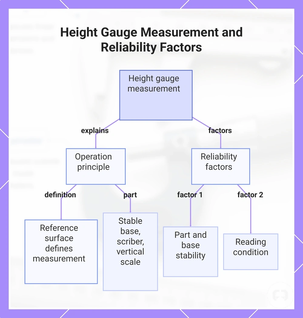
Height gauges are precision measuring tools that depend on a reference surface to establish vertical dimensions and layout marks. A stable base moves across a surface plate or other flat reference while a scriber or probe is positioned using the vertical scale. The measurement relationship is defined by the reference surface.
When a workpiece is supported on a stable reference surface, a height gauge can be used for comparative checks, vertical dimensions, or layout marking by referencing the same flat surface. For example, a scriber or probe may compare the layout height of two features only when both the workpiece and the reference surface remain stable. Reading reliability may depend on part stability, base contact, and reading condition rather than on the height gauge alone.
This chart shows how height gauges rely on a reference surface for measurement and what factors affect reading reliability.
Precision Gauges and Gauge Sets for Fixed Checks
Precision gauges and gauge sets are fixed-reference tools used to verify whether a feature matches a known size or limit rather than providing a continuous measurement reading. They compare a workpiece with a reference value to support verification instead of displaying a variable dimension. Precision gauges include gauge blocks, plug gauges, ring gauges, snap gauges, pin gauges, and feeler gauges. This fixed-reference approach distinguishes verification from continuous measurement.
When a feature is checked against a known reference, the result is based on comparison rather than a displayed measurement. For example, a plug gauge may help verify an internal feature, while a ring gauge may compare an external feature against its intended fit condition. Go/no-go logic represents a limit-based decision, although interpretation may still depend on the reference value, tolerance, and gauge condition. These examples illustrate verification through reference and fit conditions.
Go/no-go checks are intended to determine whether a feature falls within a defined limit rather than identify its exact size. Gauge blocks provide a reference value for comparison, while feeler gauges may verify a gap or clearance against a known condition. Calibration procedures remain outside the scope of this section.
| Gauge type | Feature checked | Reference or limit condition | What the result means |
|---|---|---|---|
| Gauge blocks | Reference dimension | Known reference value | Supports comparison against a fixed reference |
| Plug gauges | Internal feature | Known size or limit | May verify whether the feature matches the intended fit condition |
| Ring gauges | External feature | Known size or limit | Supports comparison of an external feature with a reference condition |
| Snap gauges | External dimension | Go/no-go limit | Provides a limit-based verification decision |
| Pin gauges | Hole or opening | Reference diameter | Supports comparison with a known size when appropriately matched |
| Feeler gauges | Gap or clearance | Reference thickness | May verify whether a clearance corresponds to the selected reference value |
Plug, ring, snap, pin, and gauge block references
Plug gauge, ring gauge, snap gauge, pin gauge, and gauge block references each correspond to a specific part feature and contact method for fixed verification. A plug gauge checks a hole, a ring gauge checks an external diameter, a snap gauge verifies an outside limit, a pin gauge checks a hole or slot, and a gauge block provides a dimensional reference value for comparison. Each gauge reference maps a known size or limit condition to the appropriate part feature.
When selecting a fixed gauge, the feature being checked should match the gauge's contact method and intended verification purpose. The result may depend on the fit condition, limit value, and gauge reliability rather than the gauge type alone. Calibration remains relevant only as a general reliability boundary, not as part of the verification process.
| Reference type | Feature checked | Contact method | Result meaning |
|---|---|---|---|
| Plug gauge | Hole | Internal contact | May verify whether the hole matches the intended limit condition |
| Ring gauge | External diameter | Encircling external contact | May compare an external diameter with a reference value |
| Snap gauge | Outside dimension | Opposing contact faces | Supports go/no-go verification against an outside limit |
| Pin gauge | Hole or slot | Inserted contact | May verify feature size when matched to the required limit condition |
| Gauge block | Dimensional reference | Reference surface contact | Provides a reference value for dimensional comparison |
Choosing a Tool Type by What Needs to Be Measured
Choose the tool type by matching it to the measured feature before considering any individual product. The final selection depends on feature type, access, range, tolerance, reading method, reference surface, and the level of measurement confidence required. More than one tool type may suit the same measurement need when conditions differ. The measured feature is the starting point for every selection.
When measuring an outside diameter, a caliper or micrometer may be suitable depending on the required tolerance and measurement confidence. Inside diameter, depth, and height measurements each rely on tools designed for those feature types, while runout and alignment are assessed with an indicator using a stable reference setup. Fixed-limit checks use gauges instead of continuous readings. These scenarios group common measurement needs by tool role.
The decision table below summarizes the main selection criteria by measurement task. Use it as a decision cue, then choose by task and measurement need when access, range, tolerance, reading method, or the reference surface could influence the final selection.
| What needs measuring | Likely tool type | Key condition to check | Why it fits |
|---|---|---|---|
| Outside diameter | Caliper or micrometer | Tolerance, range, and access | Matches external dimensional measurement needs |
| Inside diameter | Caliper or inside micrometer | Feature access and measuring range | Supports internal dimension checks |
| Depth | Depth gauge or depth micrometer | Reference surface and feature depth | Measures recessed features from a stable reference |
| Height | Height gauge | Reference surface stability | Supports vertical dimensions and layout checks |
| Runout or alignment | Dial indicator or dial test indicator | Reference setup and reading method | Evaluates relative movement rather than fixed dimensions |
| Fixed-limit checks | Precision gauge | Known limit condition | Verifies a feature against a reference value |
The final decision should be based on how the measured feature, feature type, access, range, tolerance, reading method, and reference surface work together. When more than one tool type appears suitable, measurement confidence may improve by choosing the tool whose design matches the inspection conditions. Product examples are intended only to illustrate tool categories and should not be treated as a guaranteed fit for every situation. Review the selection criteria before comparing individual examples.
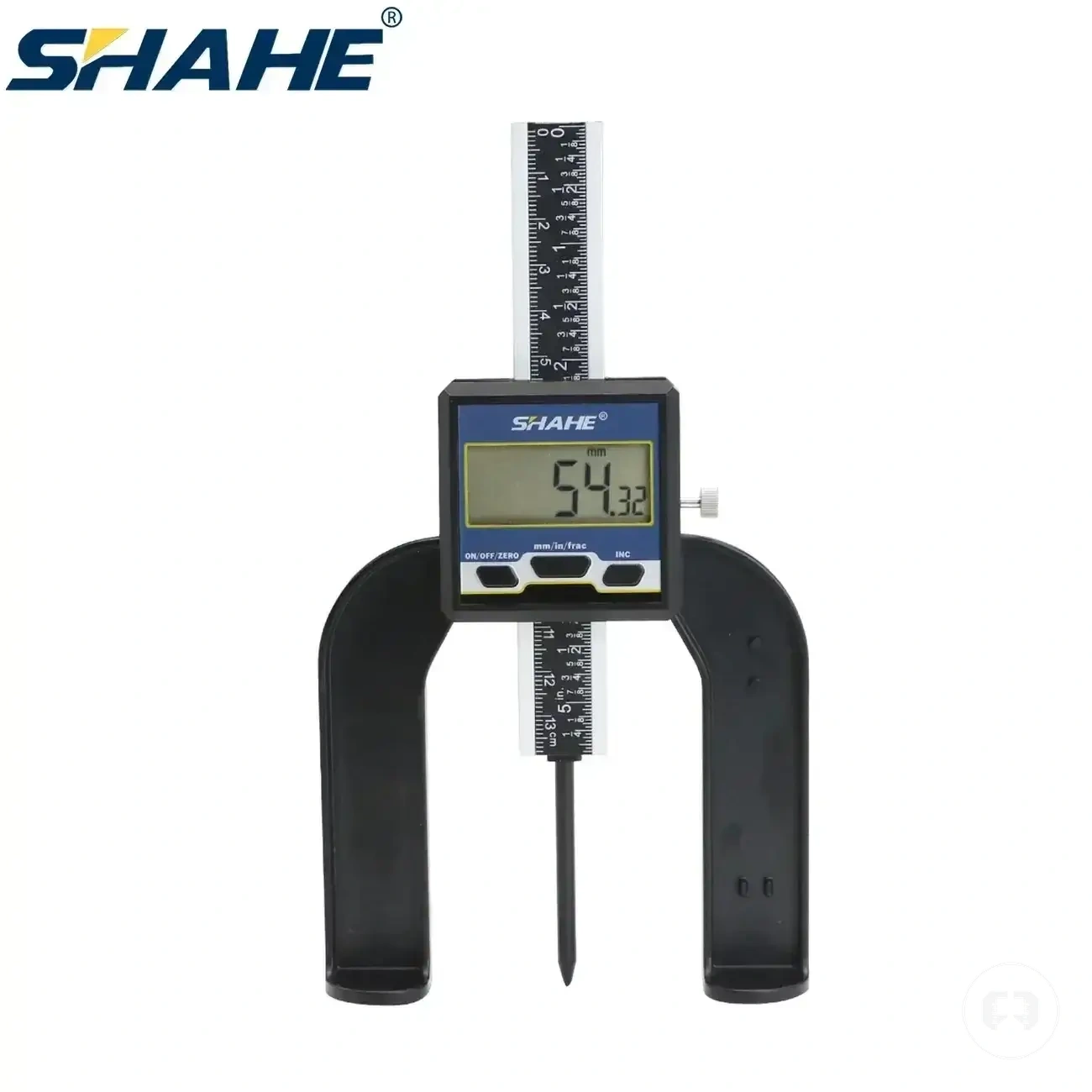
The products below are useful examples for comparing available options. Before buying, check that the compatibility criteria, key features, and product details match your needs.